Community
- Forums Home
- >
- AutoCAD Electrical Community
- >
- AutoCAD Electrical Forum
- >
- Re: Current Stab Test Switch
AutoCAD Electrical Forum
Welcome to Autodesk’s AutoCAD Electrical Forums. Share your knowledge, ask questions, and explore popular AutoCAD Electrical topics.
Turn on suggestions
Auto-suggest helps you quickly narrow down your search results by suggesting possible matches as you type.
Reply
Topic Options
- Subscribe to RSS Feed
- Mark Topic as New
- Mark Topic as Read
- Float this Topic for Current User
- Bookmark
- Subscribe
- Printer Friendly Page
Message 1 of 25
10-10-2011
09:46 AM
- Mark as New
- Bookmark
- Subscribe
- Mute
- Subscribe to RSS Feed
- Permalink
- Report
10-10-2011
09:46 AM
Current Stab Test Switch
Does ACE have anything like a FT-1 test switch? i am new to the software, and cant seem to find anything close.
David
Everyone has a photographic memory,
some just don't have film.
Everyone has a photographic memory,
some just don't have film.
24 REPLIES 24
Message 2 of 25
10-10-2011
11:16 AM
- Mark as New
- Bookmark
- Subscribe
- Mute
- Subscribe to RSS Feed
- Permalink
- Report
10-10-2011
11:16 AM
I haven't seen anything in the included libraries. We had been showing the FT-1's in a similar fashion to how we've historically shown GE test blocks. I have seen an FT-1 block on Siemen's breaker drawings that we may adapt to our use, but I'm still trying to work out all the kinks in a dynamic block that would let me alter the region that the switch or plug shorts around.
Hope that makes sense.
.
.
.
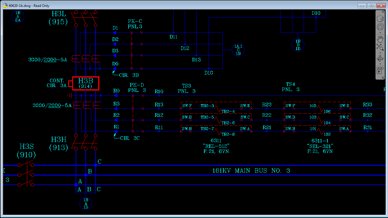
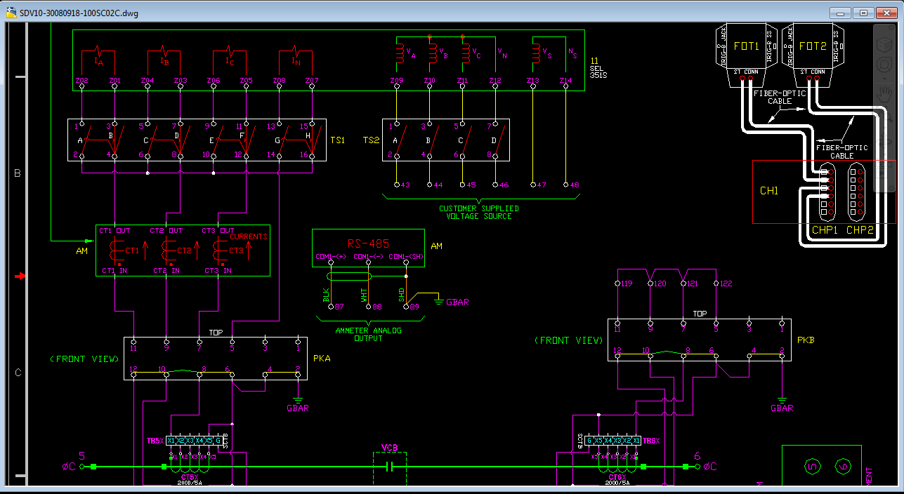
Maybe these will help. First is how we're traditionally drawn test blocks and FT-1 switches. (Example shown for a short around as well as a short out.) The second is how Siemens show pretty much the same things on their schematics. It is far less "schematic" than it is a wiring diagram in my opinion, but it works.
--------------
Joe Weaver
Principle Associate Engineer - Nashville Electric Service
P&C Committee Chair – SDS Industry Consortium
Joe Weaver
Principle Associate Engineer - Nashville Electric Service
P&C Committee Chair – SDS Industry Consortium
Message 3 of 25
10-10-2011
11:58 AM
- Mark as New
- Bookmark
- Subscribe
- Mute
- Subscribe to RSS Feed
- Permalink
- Report
10-10-2011
11:58 AM
Well the second pic is how we show it here. 1 good thing is we always use the same config, 1-2 and 19-20 are pass through, 3-18 are shorted config. I guess the next step is to figure out best way to make the block.
David
Everyone has a photographic memory,
some just don't have film.
Everyone has a photographic memory,
some just don't have film.
Message 4 of 25
10-10-2011
12:08 PM
- Mark as New
- Bookmark
- Subscribe
- Mute
- Subscribe to RSS Feed
- Permalink
- Report
10-10-2011
12:08 PM
@davidhall wrote:Well the second pic is how we show it here. 1 good thing is we always use the same config, 1-2 and 19-20 are pass through, 3-18 are shorted config. I guess the next step is to figure out best way to make the block.
Who do you buy breakers from? If your spec includes CAD drawings you make have something already...
--------------
Joe Weaver
Principle Associate Engineer - Nashville Electric Service
P&C Committee Chair – SDS Industry Consortium
Joe Weaver
Principle Associate Engineer - Nashville Electric Service
P&C Committee Chair – SDS Industry Consortium
Message 5 of 25
10-10-2011
02:22 PM
- Mark as New
- Bookmark
- Subscribe
- Mute
- Subscribe to RSS Feed
- Permalink
- Report
10-10-2011
02:22 PM
Most of them come from Mitsubishi. We typically dont show it in that form, although the vendor drawing does. Our DC and AC schemes are drawn separately.
David
Everyone has a photographic memory,
some just don't have film.
Everyone has a photographic memory,
some just don't have film.
Message 6 of 25
10-11-2011
06:39 AM
- Mark as New
- Bookmark
- Subscribe
- Mute
- Subscribe to RSS Feed
- Permalink
- Report
10-11-2011
06:39 AM
Shoot me an email at jweaver @ nespower . com (Remove spaces.)
--------------
Joe Weaver
Principle Associate Engineer - Nashville Electric Service
P&C Committee Chair – SDS Industry Consortium
Joe Weaver
Principle Associate Engineer - Nashville Electric Service
P&C Committee Chair – SDS Industry Consortium
Message 7 of 25
10-19-2011
01:54 PM
- Mark as New
- Bookmark
- Subscribe
- Mute
- Subscribe to RSS Feed
- Permalink
- Report
10-19-2011
01:54 PM
I am so close to getting this figured out! I was able to make the blocks Parent and child, the child can read from the parent for "Pinlist" but I can t seem to get the parent to pick its pins
David
Everyone has a photographic memory,
some just don't have film.
Everyone has a photographic memory,
some just don't have film.
Message 8 of 25
10-20-2011
05:42 AM
- Mark as New
- Bookmark
- Subscribe
- Mute
- Subscribe to RSS Feed
- Permalink
- Report
10-20-2011
05:42 AM
Are you putting the parent's pins in as the COILPINS? That's where they go even if they aren't coils. For example, the parent symbol for our SEL (and any IED) relays is the power supply. I just put those pins in that field in the pinlist database. Once I choose the device I want to use from the lookup table, the coil pins get added to the parent symbol.
For a PK block I just used the first set of pins as the parent. And since we aren't building terminal strips but using premade blocks, I had to make them as P-C symbols and let the first terminal be the parent.
Hope that helps.
--------------
Joe Weaver
Principle Associate Engineer - Nashville Electric Service
P&C Committee Chair – SDS Industry Consortium
Joe Weaver
Principle Associate Engineer - Nashville Electric Service
P&C Committee Chair – SDS Industry Consortium
Message 9 of 25
10-20-2011
06:22 AM
- Mark as New
- Bookmark
- Subscribe
- Mute
- Subscribe to RSS Feed
- Permalink
- Report
10-20-2011
06:22 AM
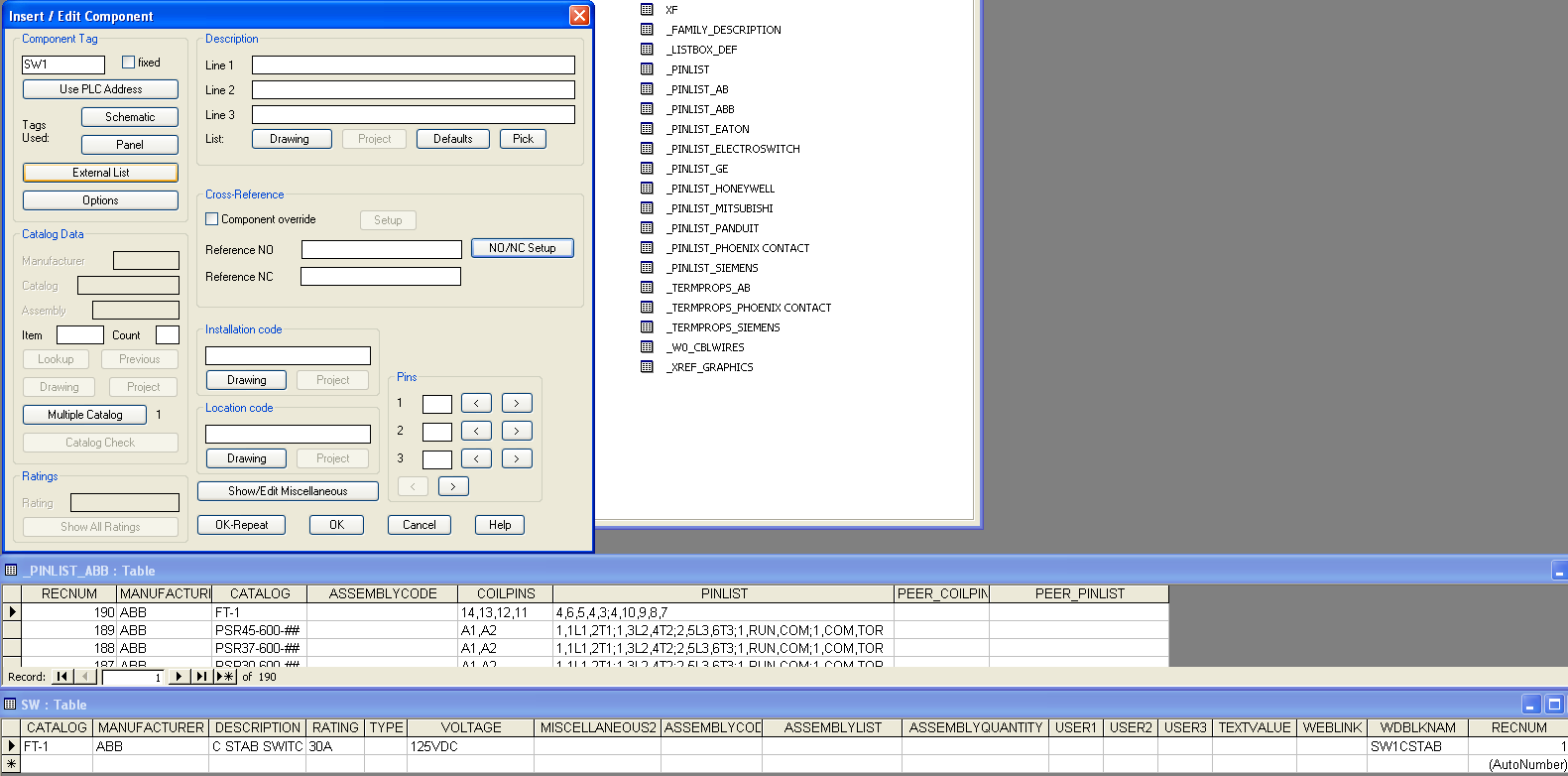
I did put it in the coil pins area. The picture shows what I have done, but I am at a loss. I know it has to be something really simple. Also, when i insert the block, my lookup button is grayed out, so maybe that has something to do with it as well
David
Everyone has a photographic memory,
some just don't have film.
Everyone has a photographic memory,
some just don't have film.
Message 10 of 25
10-20-2011
06:38 AM
- Mark as New
- Bookmark
- Subscribe
- Mute
- Subscribe to RSS Feed
- Permalink
- Report
10-20-2011
06:38 AM
The greyed out lookup button sounds like you still have the families mixed up. (SS vs SW) Did you purge the drawing of the old blocks before trying again? I find that helps.
Post the parent block too, if you don't mind. Having a look at that might help.
--------------
Joe Weaver
Principle Associate Engineer - Nashville Electric Service
P&C Committee Chair – SDS Industry Consortium
Joe Weaver
Principle Associate Engineer - Nashville Electric Service
P&C Committee Chair – SDS Industry Consortium
Message 11 of 25
10-20-2011
06:40 AM
- Mark as New
- Bookmark
- Subscribe
- Mute
- Subscribe to RSS Feed
- Permalink
- Report
10-20-2011
06:40 AM
I have tried erase, purge, close AE and reopen, nothing is working. Do you need the child as well, or the DB?
David
Everyone has a photographic memory,
some just don't have film.
Everyone has a photographic memory,
some just don't have film.
Message 12 of 25
10-20-2011
07:00 AM
- Mark as New
- Bookmark
- Subscribe
- Mute
- Subscribe to RSS Feed
- Permalink
- Report
10-20-2011
07:00 AM
I FIGURED IT OUT!!!!!! I didn't have a CAT attribute in my block for some reason.
David
Everyone has a photographic memory,
some just don't have film.
Everyone has a photographic memory,
some just don't have film.
Message 13 of 25
10-20-2011
07:09 AM
- Mark as New
- Bookmark
- Subscribe
- Mute
- Subscribe to RSS Feed
- Permalink
- Report
10-20-2011
07:09 AM
Well at first I thought the problem might be the filename. The first 5 characters are important. HSW1CSTAB has a C in the 5th slot and I didn't think that was kosher. Turns out that wasn't it. As I tried recreating the block from an exploded copy of yours, I ran the symbol audit on it. You were missing the CAT & MFG attributes. So there was no place for lookup info to go, hence the greyed out button.
Try this one.
--------------
Joe Weaver
Principle Associate Engineer - Nashville Electric Service
P&C Committee Chair – SDS Industry Consortium
Joe Weaver
Principle Associate Engineer - Nashville Electric Service
P&C Committee Chair – SDS Industry Consortium
Message 14 of 25
10-20-2011
07:11 AM
- Mark as New
- Bookmark
- Subscribe
- Mute
- Subscribe to RSS Feed
- Permalink
- Report
10-20-2011
07:11 AM
Glad you got it worked out!
--------------
Joe Weaver
Principle Associate Engineer - Nashville Electric Service
P&C Committee Chair – SDS Industry Consortium
Joe Weaver
Principle Associate Engineer - Nashville Electric Service
P&C Committee Chair – SDS Industry Consortium
Message 15 of 25
10-20-2011
07:13 AM
- Mark as New
- Bookmark
- Subscribe
- Mute
- Subscribe to RSS Feed
- Permalink
- Report
10-20-2011
07:13 AM
Thanks!! Should I use the _ in the 5th position normally?
David
Everyone has a photographic memory,
some just don't have film.
Everyone has a photographic memory,
some just don't have film.
Message 16 of 25
10-20-2011
07:17 AM
- Mark as New
- Bookmark
- Subscribe
- Mute
- Subscribe to RSS Feed
- Permalink
- Report
10-20-2011
07:17 AM
That is what the symbol builder wanted to put there as I finished the block. I normally let it decide that first part based on what I've chosen in the fields above it. But you have to watch it when editing an existing block. Mine wants to insert extra charachters now and then. The part after the underscore is where I put my descriptive text.
Also, I noticed this and forgot to fix it, but the wire connection points may not all be right at the end of your lines. The symbol audit said the wire connections weren't in line with the insertion point. Then too it may be complaining about the lower set and that's not a real issue. The top set are though.
--------------
Joe Weaver
Principle Associate Engineer - Nashville Electric Service
P&C Committee Chair – SDS Industry Consortium
Joe Weaver
Principle Associate Engineer - Nashville Electric Service
P&C Committee Chair – SDS Industry Consortium
Message 17 of 25
10-20-2011
07:29 AM
- Mark as New
- Bookmark
- Subscribe
- Mute
- Subscribe to RSS Feed
- Permalink
- Report
10-20-2011
07:29 AM
I snapped those right to the end of the line. Isn't that where they are supposed to be?
David
Everyone has a photographic memory,
some just don't have film.
Everyone has a photographic memory,
some just don't have film.
Message 18 of 25
10-20-2011
07:38 AM
- Mark as New
- Bookmark
- Subscribe
- Mute
- Subscribe to RSS Feed
- Permalink
- Report
10-20-2011
07:38 AM
Yep. Like I said, it could be the two bottom ones it is complaining about. And just because it says something is an error, doesn't mean it really is. In this case not all of the connection points CAN be in line with the insertion point.
--------------
Joe Weaver
Principle Associate Engineer - Nashville Electric Service
P&C Committee Chair – SDS Industry Consortium
Joe Weaver
Principle Associate Engineer - Nashville Electric Service
P&C Committee Chair – SDS Industry Consortium
Message 19 of 25
10-20-2011
07:52 AM
- Mark as New
- Bookmark
- Subscribe
- Mute
- Subscribe to RSS Feed
- Permalink
- Report
10-20-2011
07:52 AM
that makes sense. Now to create some SEL relays and stuff. I might get this thing working sooner than I thought
David
Everyone has a photographic memory,
some just don't have film.
Everyone has a photographic memory,
some just don't have film.
Message 20 of 25
10-20-2011
08:05 AM
- Mark as New
- Bookmark
- Subscribe
- Mute
- Subscribe to RSS Feed
- Permalink
- Report
10-20-2011
08:05 AM
Do you want to look at ours? I have the Pwr. Supply, Input and Output blocks. That is about all you need.
Plus I have pinlists done for several of them.
--------------
Joe Weaver
Principle Associate Engineer - Nashville Electric Service
P&C Committee Chair – SDS Industry Consortium
Joe Weaver
Principle Associate Engineer - Nashville Electric Service
P&C Committee Chair – SDS Industry Consortium
Reply
Topic Options
- Subscribe to RSS Feed
- Mark Topic as New
- Mark Topic as Read
- Float this Topic for Current User
- Bookmark
- Subscribe
- Printer Friendly Page

