Community
Civil 3D Forum
Welcome to Autodesk’s Civil 3D Forums. Share your knowledge, ask questions, and explore popular AutoCAD Civil 3D topics.
Turn on suggestions
Auto-suggest helps you quickly narrow down your search results by suggesting possible matches as you type.
Reply
Topic Options
- Subscribe to RSS Feed
- Mark Topic as New
- Mark Topic as Read
- Float this Topic for Current User
- Bookmark
- Subscribe
- Printer Friendly Page
Message 1 of 12
Anonymous
8200 Views, 11 Replies
01-31-2013
03:45 PM
- Mark as New
- Bookmark
- Subscribe
- Mute
- Subscribe to RSS Feed
- Permalink
- Report
01-31-2013
03:45 PM
I am having trouble creating a retaining wall subassembly that is equipped with varying height in order to follow an existing ground surface. I would like to find out how to attatch a point towards the top of the wall to the existing ground surface, so the wall height automatically adjusts to reach the top of the road cut.
The design is for a basic road along a steep slope. Before proceeding with the left side of the assembly, I wanted to create this varying height retaining wall.
I have attached an image of the assembly for reference. The ultmite goal would be to have the wall height vary along the corridor to meet the existing ground just below the top of wall.
Any help would be greatly appreciated. Using Civil 3D 2013
Cheers
Solved! Go to Solution.
Solved by sjg. Go to Solution.
11 REPLIES 11
Message 2 of 12
01-31-2013
04:06 PM
- Mark as New
- Bookmark
- Subscribe
- Mute
- Subscribe to RSS Feed
- Permalink
- Report
01-31-2013
04:06 PM
This is what the RetainWallVertical subassembly does.
Fred Ernst, PE
C3D 2024
Ernst Engineering
www.ernstengineering.com
Message 3 of 12
Anonymous
in reply to:
Anonymous
02-05-2013
09:30 AM
- Mark as New
- Bookmark
- Subscribe
- Mute
- Subscribe to RSS Feed
- Permalink
- Report
02-05-2013
09:30 AM
Using the RetainWallVertical, what parameter would be the appropriate one to attach to the surface? I'm assuming it would be the Top Height.
I'm not sure how to attach parameters to the target surface. I've tried going through the Assembly Properties, under the Construction tab, and using Parameter Reference, but I don't see the correct option available in the "Get Value From" dropdown list.
Message 4 of 12
02-05-2013
10:36 AM
- Mark as New
- Bookmark
- Subscribe
- Mute
- Subscribe to RSS Feed
- Permalink
- Report
02-05-2013
10:36 AM
It will be a target within your corridor, similar to a target for daylighting.
Steve Goessling
Land Consultants
Civil3D 2015
Windows 7, 64 bit
Intel i7 2600 @ 3.40Ghz
16 GB RAM
Nvidia Quadro 600
Land Consultants
Civil3D 2015
Windows 7, 64 bit
Intel i7 2600 @ 3.40Ghz
16 GB RAM
Nvidia Quadro 600
Message 6 of 12
02-05-2013
11:06 AM
- Mark as New
- Bookmark
- Subscribe
- Mute
- Subscribe to RSS Feed
- Permalink
- Report
02-05-2013
11:06 AM
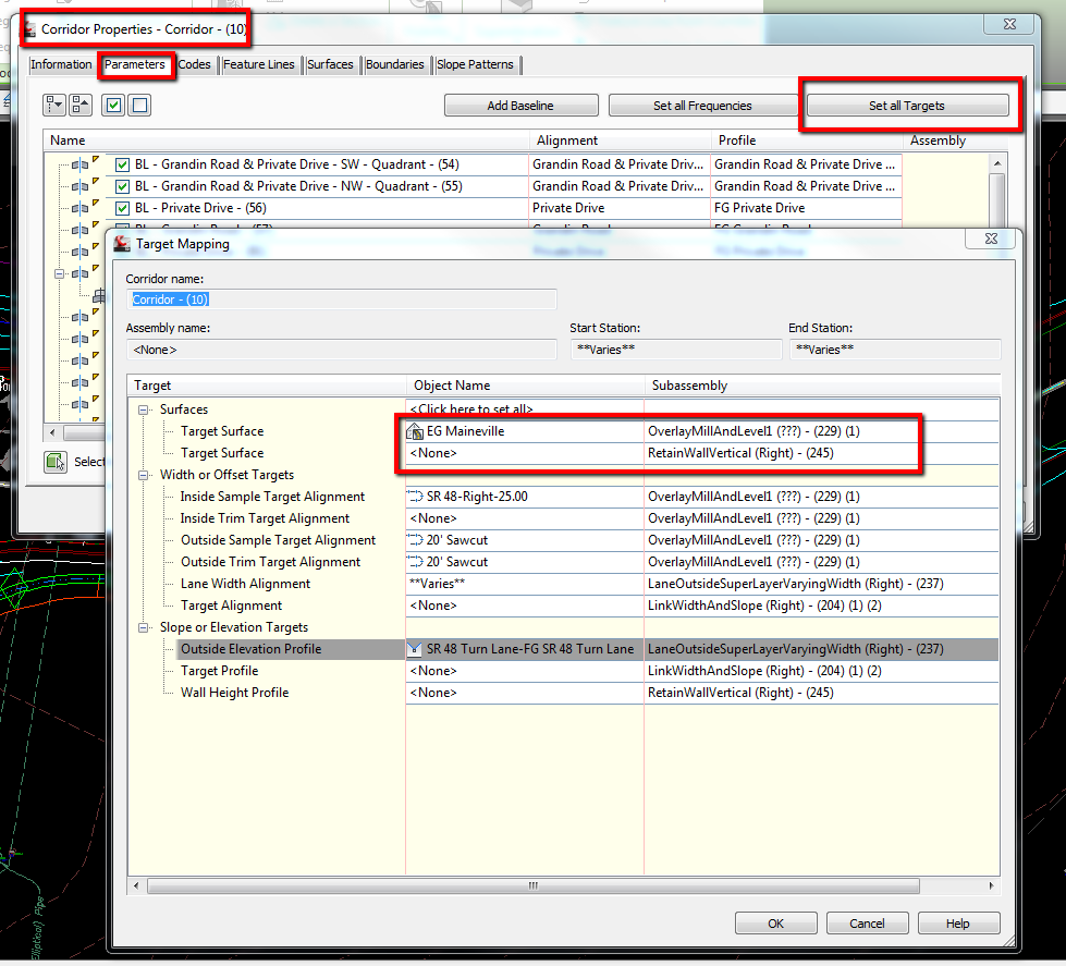
See attached image. Select corridor, right click, select corridor properties, Under the parameter tab, select set all target, you should see RetainWallVeritcal under the surfaces section. set your surface you want the wall to daylight to.
Steve Goessling
Land Consultants
Civil3D 2015
Windows 7, 64 bit
Intel i7 2600 @ 3.40Ghz
16 GB RAM
Nvidia Quadro 600
Land Consultants
Civil3D 2015
Windows 7, 64 bit
Intel i7 2600 @ 3.40Ghz
16 GB RAM
Nvidia Quadro 600
Message 8 of 12
02-05-2013
11:32 AM
- Mark as New
- Bookmark
- Subscribe
- Mute
- Subscribe to RSS Feed
- Permalink
- Report
02-05-2013
11:32 AM
Please pick Accept as Solution, if that answered your question.
Steve Goessling
Land Consultants
Civil3D 2015
Windows 7, 64 bit
Intel i7 2600 @ 3.40Ghz
16 GB RAM
Nvidia Quadro 600
Land Consultants
Civil3D 2015
Windows 7, 64 bit
Intel i7 2600 @ 3.40Ghz
16 GB RAM
Nvidia Quadro 600
Message 9 of 12
Anonymous
in reply to:
Anonymous
02-06-2013
11:29 AM
- Mark as New
- Bookmark
- Subscribe
- Mute
- Subscribe to RSS Feed
- Permalink
- Report
02-06-2013
11:29 AM
Thanks again for the previous help. I was able to link the top of the retaining wall to the existing surface, but now I would like to link the wall footing to a certain depth relative to the same existing surface.
Essentially, I want to maintain a 5' width of horizontal cover between the left edge of the footing and the existing surface. I believe this could be accomplished by somehow creating a variable footing cover height relative to a 5' horizontal distance from the surface in combination with a daylight subassembly.
The purpose of this 5' horizontal cover is to eliminate the need for a fill slope stemming off the back of the wall. The proposed road location is along a very steep slope where a fill slope is undesirable. With the footing being buried deep enough, no fill slope will be needed.
I have attached an image of my assembly with some text to detail my idea.
Any help would be great.
Thanks in advance
Message 10 of 12
02-06-2013
12:00 PM
- Mark as New
- Bookmark
- Subscribe
- Mute
- Subscribe to RSS Feed
- Permalink
- Report
02-06-2013
12:00 PM
"The proposed road location is along a very steep slope where a fill slope is undesirable."
This wall scenario may be a better choice for this stretch of steep slope where you don't have much lateral purchase. Also, your 5' offset scenario doesn't necessaritly ensure a minimum footing depth is always achieved.
Coordinate with your structural engineer on this.

Fred Ernst, PE
C3D 2024
Ernst Engineering
www.ernstengineering.com
Message 11 of 12
02-06-2013
02:13 PM
- Mark as New
- Bookmark
- Subscribe
- Mute
- Subscribe to RSS Feed
- Permalink
- Report
02-06-2013
02:13 PM
I tried the RetainWallToLowSide subassembly and ran it through the corridor, but I'm still having trouble burying the bottom of the wall deep enough below the design profile.
I have attached another image illustrating an example of a problem area at a station along the alignment. As you can see, the bottom of the retaining wall isn't deep enough and protrudes out of the slope. I want it to be buried deep enough so that there exists the 5' horizontal cover from the bottom of the wall outwards.
Message 12 of 12
02-07-2013
05:16 AM
- Mark as New
- Bookmark
- Subscribe
- Mute
- Subscribe to RSS Feed
- Permalink
- Report
02-07-2013
05:16 AM
It got flipped on you because you went into a little bit of Cut on that side. You could use a Conditional Cut/Fill on that side and control the Side parameter for this wall Subassembly on this steep slope side. If you flip the Side parameter and specify an appropriate Footing Cover everything should look reasonable.
If you really want that 5' offset footing cover/depth, I think you're going to have to go SAC on it, because the footing cover for this SA will not take an elevation.
Fred Ernst, PE
C3D 2024
Ernst Engineering
www.ernstengineering.com
Reply
Topic Options
- Subscribe to RSS Feed
- Mark Topic as New
- Mark Topic as Read
- Float this Topic for Current User
- Bookmark
- Subscribe
- Printer Friendly Page


.JPG)
.jpg)
.jpg)