Community
- Forums Home
- >
- Civil 3D Community
- >
- Civil 3D Forum
- >
- Re: Profile View empty or missing- Cave-in -section view
Civil 3D Forum
Welcome to Autodesk’s Civil 3D Forums. Share your knowledge, ask questions, and explore popular AutoCAD Civil 3D topics.
Turn on suggestions
Auto-suggest helps you quickly narrow down your search results by suggesting possible matches as you type.
Reply
Topic Options
- Subscribe to RSS Feed
- Mark Topic as New
- Mark Topic as Read
- Float this Topic for Current User
- Bookmark
- Subscribe
- Printer Friendly Page
Message 1 of 6
11-28-2012
05:43 PM
- Mark as New
- Bookmark
- Subscribe
- Mute
- Subscribe to RSS Feed
- Permalink
- Report
11-28-2012
05:43 PM
Profile View empty or missing- Cave-in -section view
Hi,
1. I had trouble with profile view of the alignment line shown. What step am i missing? Are there things that is turned off?
2. How can I best come up with the right volume to fill.
3. Do I need to learn the grading tools? or could i get buy with a section profile from the alignment. ( it is not even an alignment yet)
4. How to I render a rock fill in this cave-in.
The attached aerial image , has survey or cogo points that are imported to surface, to become surface points. . So I wanted to create a surface profile below and an outline of fill above it. Iideally the side profile would look like a trapezoid, where the base is the surface proile and top would be the design embankment.
But the reason , a surveying crew went down and took shots at the shoreline and a couple shots around the cave-in walls (higher elevation on the cave-in wall cannot be surveyed, although I coud have used a laser , did not) is so that a more accurate volume of the cave in can be obtained. I tried to label how far the road edge is from edge of the cave-in . Norice the higher elevations are the top edge around the cave in area.
The ouline for the embankment will be a mild slope then breaks to
a more steep slope. like 4 :1 , then 1.5:1
Again, I'd like to thank the forum for helping me out. I'll be working on this 10:00 pm tonight. So your response will be
response will be very much appreciated.
Happy Holidays
5 REPLIES 5
Message 2 of 6
11-30-2012
07:29 AM
- Mark as New
- Bookmark
- Subscribe
- Mute
- Subscribe to RSS Feed
- Permalink
- Report
11-30-2012
07:29 AM
I am having trouble enderstanding what you are trying to do here. It seems that you are missing some data in order to get accurate results. Are you tring to fill in everything to the road edge?
Grading may be the best way to do this, then you can create a surface from the grading, then compare the existing and proposed graded surfaces for volumes.
Seth Hall
Product Owner
Model Builder
Message 3 of 6
11-30-2012
11:23 AM
- Mark as New
- Bookmark
- Subscribe
- Mute
- Subscribe to RSS Feed
- Permalink
- Report
11-30-2012
11:23 AM
Hi,
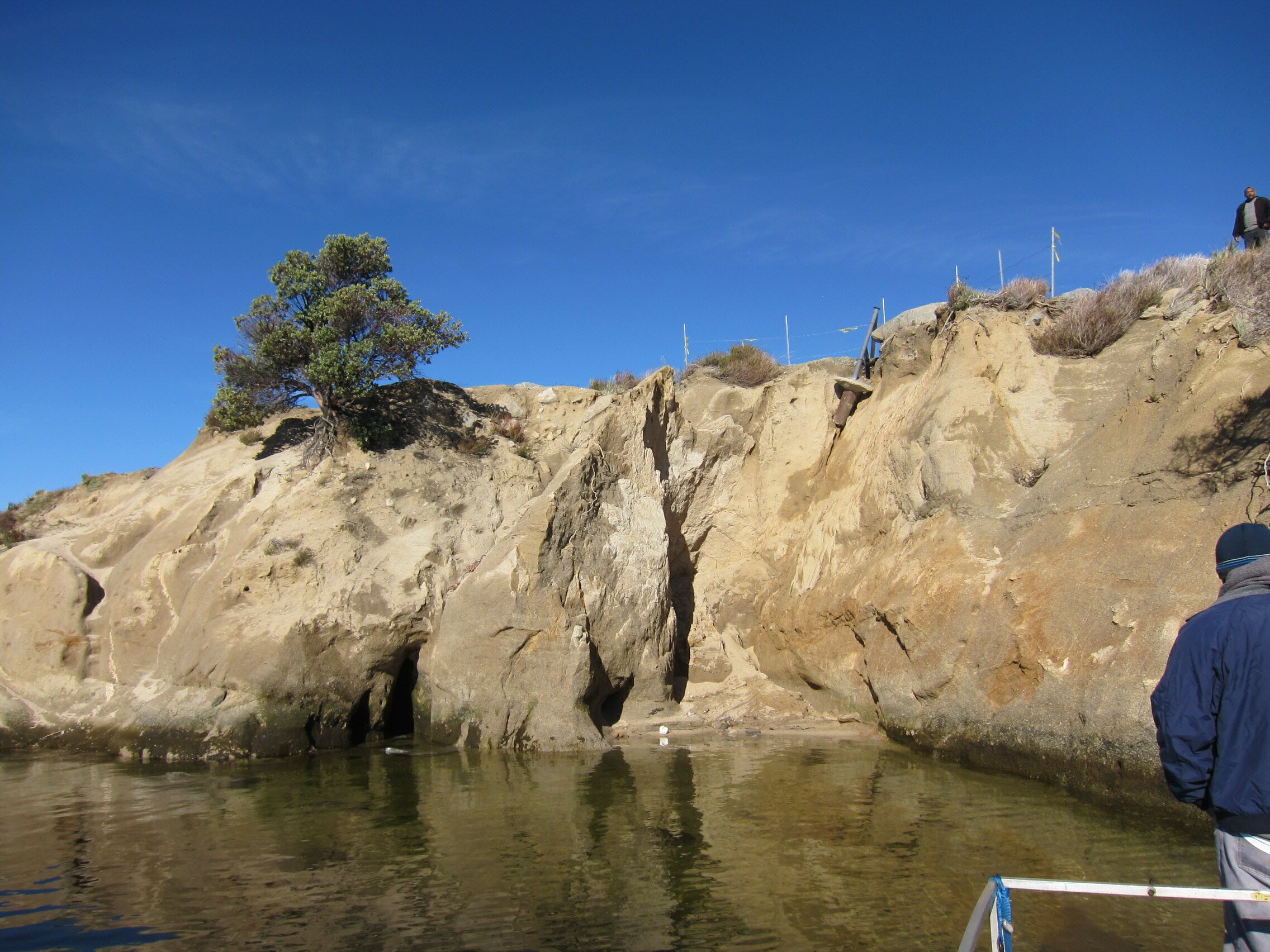
The image sattach shows the Cave-in area of an road embankment next to a lake reservoir. Surveying points were shot around the top of the edge of the cliff near the road , a few shots around the cliff wall ( just three shots) , and shots to the presumed toe line of a rock fill embankment. This rock fill is the missing volume of the embankment. From these points, a Civil 3d surface was generated. Now , a red line was drawn over the surface and from it an alignment can be created , correct? . So once an alignment is created then a surface profile can be created. The surface profile will be the lower boundary profile and the upper boundary profile,consist of mild slope of 3:1 for first the 5' drop elevation then a break to a steeper slope of 1.5:1 for the final 20-25' near the presume toe line of a rock fill (This will be the design surface) . I'll probably extend the toe line another 5 feet so the force of the waves will not be a major factor. This probably requires additional analysis from a army corps of engineer manuals.
So the help I need is,
1.Getting the volume between the two boundaries and showing the volumes appearing as rock materials. I'd like to show the filled volume draped with these photos (use as a background) is it possible?
2. A section profile showing the the two boundaries ....showing the final elevation for the rock fill toe, the water level, ......
What's important also is draping the model with images.
thanks. Appriciate all the help again.
Message 4 of 6
11-30-2012
11:54 AM
- Mark as New
- Bookmark
- Subscribe
- Mute
- Subscribe to RSS Feed
- Permalink
- Report
11-30-2012
11:54 AM
1. getting the volume would be easiest if you had two surfaces, which from what I understand would be better served by using grading. You can drape imagery as well: http://beingcivil.typepad.com/my_weblog/2009/05/draping-images-101.html
2. using that red line you can create an alignment "from object" you can then draw a surface profile from the EG then from the proposed surface, then superimpose them onto the same profile view for comparison.
Seth Hall
Product Owner
Model Builder
Message 5 of 6
11-30-2012
01:07 PM
- Mark as New
- Bookmark
- Subscribe
- Mute
- Subscribe to RSS Feed
- Permalink
- Report
11-30-2012
01:07 PM
Hi again,
How do I create the design surface profile.? The one above the E.G. Yes I have the desired slope. Do start creating points (assigning x,y,z's) to create a a feature line then offsetting line to the left and right of the original feature line?
or do i go to the profile tools?
thanks
Message 6 of 6
11-30-2012
01:25 PM
- Mark as New
- Bookmark
- Subscribe
- Mute
- Subscribe to RSS Feed
- Permalink
- Report
11-30-2012
01:25 PM
You can create a layout profile that will represent the proposed surface, but it will not create the surface. You can create the surface first then sample that new surface.
Seth Hall
Product Owner
Model Builder
Reply
Topic Options
- Subscribe to RSS Feed
- Mark Topic as New
- Mark Topic as Read
- Float this Topic for Current User
- Bookmark
- Subscribe
- Printer Friendly Page
Forums Links
Can't find what you're looking for? Ask the community or share your knowledge.
Post to forums

