Community
Civil 3D Forum
Welcome to Autodesk’s Civil 3D Forums. Share your knowledge, ask questions, and explore popular AutoCAD Civil 3D topics.
Turn on suggestions
Auto-suggest helps you quickly narrow down your search results by suggesting possible matches as you type.
Reply
Topic Options
- Subscribe to RSS Feed
- Mark Topic as New
- Mark Topic as Read
- Float this Topic for Current User
- Bookmark
- Subscribe
- Printer Friendly Page
Message 1 of 17
04-09-2013
06:35 AM
- Mark as New
- Bookmark
- Subscribe
- Mute
- Subscribe to RSS Feed
- Permalink
- Report
04-09-2013
06:35 AM
Looking for area between profiles...
Hello I am looking to calculate an area between to profiles(sq ft). I basically have a profile along GL of a wall along with a profile at FG along the back side of wall at the front face of panel. I need to calculate the area between the two profiles as that's how the wall construction is billed. Any help would be appreciated. Thanks
Civil 3D 2014
i7-3930K Overclocked
32 GB Ram
Windows 7 Professional
i7-3930K Overclocked
32 GB Ram
Windows 7 Professional
16 REPLIES 16
Message 2 of 17
04-09-2013
06:40 AM
- Mark as New
- Bookmark
- Subscribe
- Mute
- Subscribe to RSS Feed
- Permalink
- Report
04-09-2013
06:40 AM
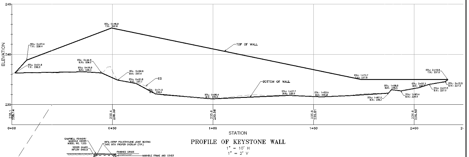
Draw a profile view for top and bottom of wall.
Superimpose top profile to bottom or vice versa.
Draw a pline closing the wall face. If the profiles close perfectly and you can turn the grid layer off, the boundary command should work.
Add a note label that will use an expression to divide the pline area by the profile view vertical exageration.
Attached is the result of the above w/o the area label.
John Mayo
Message 3 of 17
04-09-2013
07:25 AM
- Mark as New
- Bookmark
- Subscribe
- Mute
- Subscribe to RSS Feed
- Permalink
- Report
04-09-2013
07:25 AM
I posed a similar question some years ago. You might find it helpful. I ended up using John's approach but it was noted there may be a way to do it with QTO.
Neil Wilson (a.k.a. neilw)
AEC Collection/C3D 2024, LDT 2004, Power Civil v8i SS1
WIN 10 64 PRO
http://www.sec-landmgt.com
AEC Collection/C3D 2024, LDT 2004, Power Civil v8i SS1
WIN 10 64 PRO
http://www.sec-landmgt.com
Message 4 of 17
04-10-2013
06:26 AM
- Mark as New
- Bookmark
- Subscribe
- Mute
- Subscribe to RSS Feed
- Permalink
- Report
04-10-2013
06:26 AM
Not sure if I fully understand what is needed, but, If the profiles are actual profiles and not drawn by hand you could get the area utilising surfaces and volumes. If you have a profile of the GL and the FG then you can create a surface for each that is 1 foot wide. then calculate the volume between the two. this will be the same as the area.
Simple math:
V=LxWxH, A=LxW there fore V=AxH but if the width of the surface is 1, then the formula breaks down to V=LxH also known as the vertical surface area between the two profiles.
Edwin Melendez
AutoCAD Civil 3D 2013 Certified Professional
Certification No. 00319327
AutoCAD Civil 3D 2013 Certified Professional
Certification No. 00319327
Message 5 of 17
04-10-2013
06:32 AM
- Mark as New
- Bookmark
- Subscribe
- Mute
- Subscribe to RSS Feed
- Permalink
- Report
04-10-2013
06:32 AM
I like that idea. I presume you mean to create a corridor from both profiles, > corridor surfaces > volume surface.
Be careful though. Make sure both corridors are based on profiles on the same alignment. If not, the top and bottom surfaces won't fully overlap and the volume could be cut in half or more than what it should be to represent the area.
Mark Green
Working on Civil 3D in Canada![]()
Message 6 of 17
04-10-2013
06:55 AM
- Mark as New
- Bookmark
- Subscribe
- Mute
- Subscribe to RSS Feed
- Permalink
- Report
04-10-2013
06:55 AM
yes, I did mean using a corridor. I Haven't had my first cup of coffee yet so I'm not running on all 8 yet. ![]()
Although it would be easier to manage, you don't actually have to have them associated to the same alignment; however, the alignments would have to be directly over one another. there are pros and cons to both. what I would do though, is make the "base" surface (corridor) just a bit wider then the "top" surface (corridor) that will prevent the error you speek of.
Edwin Melendez
AutoCAD Civil 3D 2013 Certified Professional
Certification No. 00319327
AutoCAD Civil 3D 2013 Certified Professional
Certification No. 00319327
Message 7 of 17
04-10-2013
09:01 AM
- Mark as New
- Bookmark
- Subscribe
- Mute
- Subscribe to RSS Feed
- Permalink
- Report
04-10-2013
09:01 AM
Kudos to you for a great suggestion.
Neil Wilson (a.k.a. neilw)
AEC Collection/C3D 2024, LDT 2004, Power Civil v8i SS1
WIN 10 64 PRO
http://www.sec-landmgt.com
AEC Collection/C3D 2024, LDT 2004, Power Civil v8i SS1
WIN 10 64 PRO
http://www.sec-landmgt.com
Message 8 of 17
04-10-2013
10:05 AM
- Mark as New
- Bookmark
- Subscribe
- Mute
- Subscribe to RSS Feed
- Permalink
- Report
04-10-2013
10:05 AM
JOHNM This is the method I will end up using. The only thing is that I am having trouble getting the expression right within the lable. Could you help with what that would look like. My vert eg is 10. Thank You
Civil 3D 2013
Message 9 of 17
04-10-2013
10:52 AM
- Mark as New
- Bookmark
- Subscribe
- Mute
- Subscribe to RSS Feed
- Permalink
- Report
04-10-2013
10:52 AM
Here are the three label styles that I have used.
The profile method is better for our workflow because we need to submit construction drawings for the wall that will include block layout, geogrid layout, anchors, etc. The superimposed profiles set this up nice. Profile sta/elv labels make it easy to draw the wall in our structural sofware that will spit out the block and geogrid layout. Surfaces and QTO add tasks/time without gains in the production cycle.
John Mayo
Message 10 of 17
04-10-2013
11:12 AM
- Mark as New
- Bookmark
- Subscribe
- Mute
- Subscribe to RSS Feed
- Permalink
- Report
04-10-2013
11:12 AM
Well that is a matter of opinion. As with most things with Civil 3D, there are more than one way to get the same result. it's just a matter of how far you want to take it and how comfortable you are with certain things. some people are not comfortable with corridors and other are not comfortable with pipes.
The time it takes to create 2 assemblies and then a quick coridor and surface is only a matter of 5 minutes tops. The production benefit is if either profile changes. You will not have to trace the profile again, just change the profile, rebuild the corridor and then check the stats of the volume surface. This takes less time than recreating the polyline. I'm sure there are other benefits with creating tables and stuff that I am not thinking of.
With that said, I do not know the specific purpose of this exercise as I do not do any work dealing with quantifying surface areas of walls.
Bottom line, choose the method you are most comfortable with and run with it like a fat kid chasing the ice cream truck!![]()
Edwin Melendez
AutoCAD Civil 3D 2013 Certified Professional
Certification No. 00319327
AutoCAD Civil 3D 2013 Certified Professional
Certification No. 00319327
Message 11 of 17
04-10-2013
02:26 PM
- Mark as New
- Bookmark
- Subscribe
- Mute
- Subscribe to RSS Feed
- Permalink
- Report
04-10-2013
02:26 PM
Yes there is opinion involved which is why I referenced the post to our workflow. We are not designing long symmetrical walls that you would typically find in transportation projects. QTO isn't going to do this and surfaces may make sense to me in our workflow if the design was constantly changing or I was running through a number of cost estimates. IMO tracing a simple pline is faster and easier to work with for our workflow. The design will not change often enough to warrant a dynamic calc.
I use corridors often for these walls using the two profiles mentioned above and one assembly. The corridor is used to harvest feature lines for a surface and 5 min's would be a long time to build one of the wall corridors I have done recently.
In our workflow the profile is required on plans for local contruction in some towns. Engineering drawings and calcs are required for walls over 3.5'-4'. Many contractors around here also bid/price these walls by face area.
John Mayo
Message 13 of 17
04-11-2013
08:41 AM
- Mark as New
- Bookmark
- Subscribe
- Mute
- Subscribe to RSS Feed
- Permalink
- Report
04-11-2013
08:41 AM
We use surfaces and since I know the "slope" of the wall, we have a "slope legend" that reports the 3d area of a specified slope. That gives us the square footage of the wall.
I can elaborate if you are interested.
Thanks,
Conan Witzel
Message 14 of 17
04-11-2013
09:08 AM
- Mark as New
- Bookmark
- Subscribe
- Mute
- Subscribe to RSS Feed
- Permalink
- Report
04-11-2013
09:08 AM
Do you mean simply a surface straight from the top, front of the wall to the bottom front? Built with feature lines or corridor targeting a profile? I've never used legends, but I presume this is the same number as '3D surface area' in the Extended Statistics. This method sounds even simpler than the one with two corridors and a volume surface.
Mark Green
Working on Civil 3D in Canada![]()
Message 15 of 17
04-11-2013
10:54 AM
- Mark as New
- Bookmark
- Subscribe
- Mute
- Subscribe to RSS Feed
- Permalink
- Report
04-11-2013
10:54 AM
We usually use a grading object set to 1000%. Under surface analysis we set it to one range with 900%+. Under the surface style you can turn on slopes to verify you are getting the correct slopes.
You set the slope legend table style to report 3d area.
This would also work with a corridor surface if you knew the slope of the wall.
It can also be dynamic (be cautious with 2013 we have had some issues.)
Works great.
Hope that helps
Conan Witzel
Message 16 of 17
04-11-2013
11:58 AM
- Mark as New
- Bookmark
- Subscribe
- Mute
- Subscribe to RSS Feed
- Permalink
- Report
04-11-2013
11:58 AM
I presume you have the grading object targeting a surface, the feature line is the top of the wall, and the alignment is directly over the feature line.
My first thoughts when I saw this post was this method, but the information originally provided led me to my original response. Good methods either way.
Edwin Melendez
AutoCAD Civil 3D 2013 Certified Professional
Certification No. 00319327
AutoCAD Civil 3D 2013 Certified Professional
Certification No. 00319327
Message 17 of 17
04-11-2013
12:52 PM
- Mark as New
- Bookmark
- Subscribe
- Mute
- Subscribe to RSS Feed
- Permalink
- Report
04-11-2013
12:52 PM
We would use a grading object only when daylighting to a surface. On the interior of a site, we might just do a really tight offset. Anything to get the slope % very high.
We generally do our curbs as .5 over and .5 up (or 100%) so anything steeper than that should be a wall.
A Corrdior would work as well and might eliminate a step with the alignment.
We started doing this way back in the LDD days and had a macro that would sum a group of 3d faces. The legend just makes it easier and dynamic (when that works!!)
Thanks,
Conan Witzel
Reply
Topic Options
- Subscribe to RSS Feed
- Mark Topic as New
- Mark Topic as Read
- Float this Topic for Current User
- Bookmark
- Subscribe
- Printer Friendly Page

