Community
- Forums Home
- >
- Civil 3D Community
- >
- Civil 3D Forum
- >
- Re: Link Slope to Elevation only works in one direction
Civil 3D Forum
Welcome to Autodesk’s Civil 3D Forums. Share your knowledge, ask questions, and explore popular AutoCAD Civil 3D topics.
Turn on suggestions
Auto-suggest helps you quickly narrow down your search results by suggesting possible matches as you type.
Reply
Topic Options
- Subscribe to RSS Feed
- Mark Topic as New
- Mark Topic as Read
- Float this Topic for Current User
- Bookmark
- Subscribe
- Printer Friendly Page
Message 1 of 12
12-18-2013
06:55 AM
- Mark as New
- Bookmark
- Subscribe
- Mute
- Subscribe to RSS Feed
- Permalink
- Report
12-18-2013
06:55 AM
I have a subassembly that will target a specific elevation. The problem I am having is that it will only work in one direction, so if I assign an elevation that is typically 2 feet higher then it only works in the cut scenario. If I switch the value of the Elevation to a lower target value then it only works in a fill scenario. This only works if I switch the sign of the slope from positive to negative to keep things equal... Basically it is ignoring the decision I made. Any ideas? I've attached some screen captures for a visual.
Solved! Go to Solution.
Solved by doni49. Go to Solution.
11 REPLIES 11
Message 2 of 12
12-22-2013
05:08 AM
- Mark as New
- Bookmark
- Subscribe
- Mute
- Subscribe to RSS Feed
- Permalink
- Report
12-22-2013
05:08 AM
Post a good clear sketch of the design problem for comment and analysis.
Fred Ernst, PE
C3D 2024
Ernst Engineering
www.ernstengineering.com
Message 3 of 12
12-22-2013
01:23 PM
- Mark as New
- Bookmark
- Subscribe
- Mute
- Subscribe to RSS Feed
- Permalink
- Report
12-22-2013
01:23 PM
In addition to the sketch Fred asked for, I'd like to see a screen shot that shows us what IS happening (i.e. one sketch showing us what you WANT and a screenshot showing us what you DO GET).
In the interim, how are P1 & AP1 defined? It sounds like you're saying that it always uses the TRUE side even when you expect it to use the FALSE side. Right?
Don Ireland
Engineering Design Technician![]()
If a reply solves your issue, please remember to click on "Accept as Solution". This will help other users looking to solve a similar issue. Thank you.
Please do not send a PM asking for assistance. That's what the forums are for. This allows everyone to benefit from the question asked and the answers given.
Message 4 of 12
12-23-2013
06:00 AM
- Mark as New
- Bookmark
- Subscribe
- Mute
- Subscribe to RSS Feed
- Permalink
- Report
12-23-2013
06:00 AM
fcernst and Don;
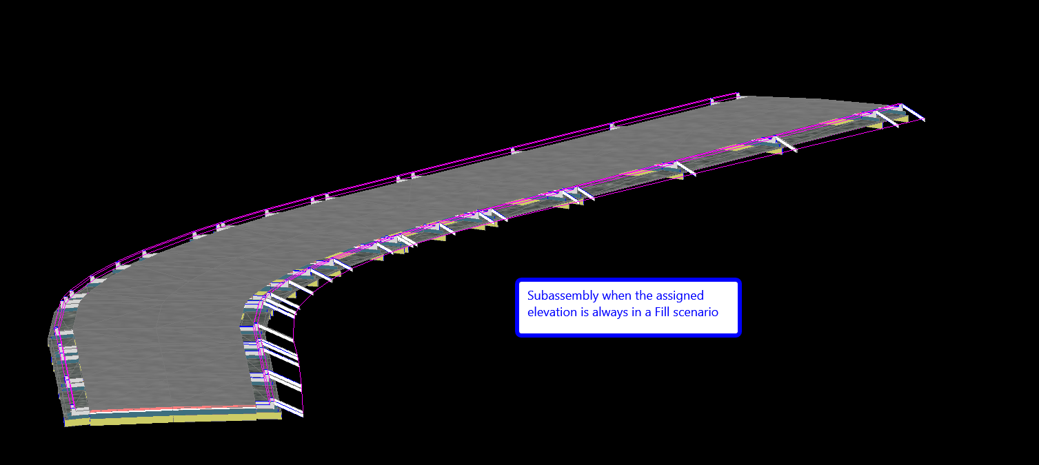
I've attached three new images of the subassembly in object viewer.
The subassembly will build just fine if it is completely in a Cut or Fill scenario.
I assigned different slopes for each scenarios to test my "Decision" in SAC... Works justs fine
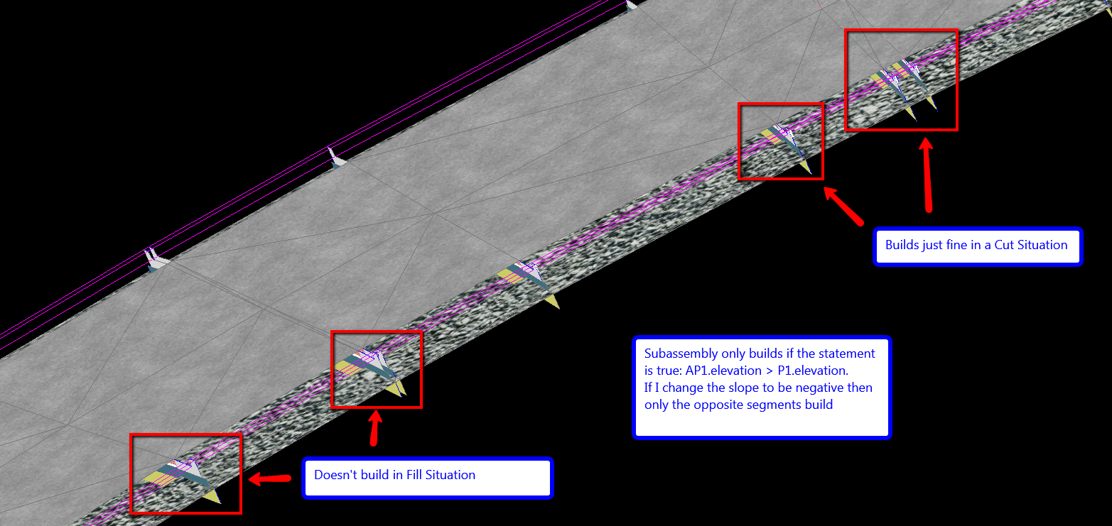
Problem is when the subassembly isn't always in just a cut or fill situation but varies.
In this situation... The subassembly will only build in a Cut scenario (True statement in my decision).
If I switch the slope to havbe a negative value... then it will only build in the Fill areas but still pulling the slopes from the True statement
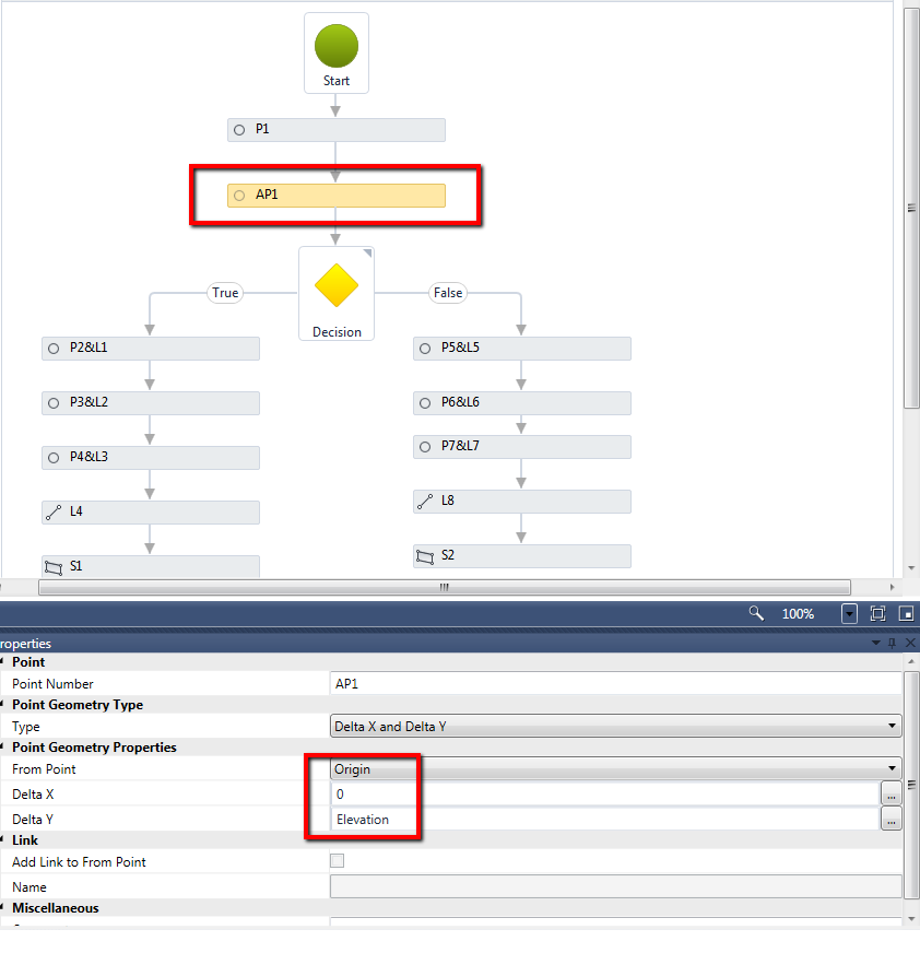
My AP1 is assigned from the Origin with Delta X Delta Y... O for X and "Elevation" for Y (See Image04)
I then compare AP1.elevation to P1.elevation to see if AP1 is greater than P1.
If true (See image01)
If False (See Image02)
Variables are in Image03.
Thanks for the assistance
Message 6 of 12
12-23-2013
07:49 AM
- Mark as New
- Bookmark
- Subscribe
- Mute
- Subscribe to RSS Feed
- Permalink
- Report
12-23-2013
07:49 AM
How is P1 defined?
AP1 is ALWAYS the same distance from the origin (unless you use the Section Editor to change individual station ranges/sections). If P1 is also a static distance from the origin, then the decision will always be the same.
Don Ireland
Engineering Design Technician![]()
If a reply solves your issue, please remember to click on "Accept as Solution". This will help other users looking to solve a similar issue. Thank you.
Please do not send a PM asking for assistance. That's what the forums are for. This allows everyone to benefit from the question asked and the answers given.
Message 7 of 12
12-23-2013
08:10 AM
- Mark as New
- Bookmark
- Subscribe
- Mute
- Subscribe to RSS Feed
- Permalink
- Report
12-23-2013
08:10 AM
P1 is defined at the origin
AP1 is defined to a set elevation
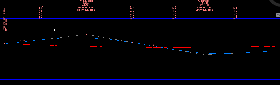
So the distance from P1.elevation to AP1.elevation should change based on the profile of the corridor.
I can see the subassembly distance change in the corridor
Here is a copy of the PKT
Message 8 of 12
12-23-2013
08:34 AM
- Mark as New
- Bookmark
- Subscribe
- Mute
- Subscribe to RSS Feed
- Permalink
- Report
12-23-2013
08:34 AM
@smizsak wrote:P1 is defined at the origin
AP1 is defined to a set elevation
So the distance from P1.elevation to AP1.elevation should change based on the profile of the corridor.
I can see the subassembly distance change in the corridor
Here is a copy of the PKT
No AP1's Y parameter is set to DELTA Y. Delta means CHANGE of a specified amount. In this case, Delta Y = Elevation and is what I'm guessing is a decimal value. If that value is 10.0, then it will be 10.0 ABOVE origin. If that value is -5.0 then it will be 5.0 BELOW the origin. Therefore, the distance between AP1 and P1 will always be the same.
Origin is always at the profile location. That's what is causing you to see the change in elevation.
EDIT: That's why you have DELTA X = 0 -- you're going 0.0 in the x direction so it's directly above or below the origin.
EDIT2: I forgot to mention that I couldn't open your file because I'm on 2012 here. When I attempted to open your file, it threw errors.
Don Ireland
Engineering Design Technician![]()
If a reply solves your issue, please remember to click on "Accept as Solution". This will help other users looking to solve a similar issue. Thank you.
Please do not send a PM asking for assistance. That's what the forums are for. This allows everyone to benefit from the question asked and the answers given.
Message 9 of 12
12-23-2013
08:54 AM
- Mark as New
- Bookmark
- Subscribe
- Mute
- Subscribe to RSS Feed
- Permalink
- Report
12-23-2013
08:54 AM
If Elevation is an Elevation Target (on the Target Parameters tab) then try setting AP1's properties to Angle and Delta Y.
Then Elevation Target to Elevation.

Don Ireland
Engineering Design Technician![]()
If a reply solves your issue, please remember to click on "Accept as Solution". This will help other users looking to solve a similar issue. Thank you.
Please do not send a PM asking for assistance. That's what the forums are for. This allows everyone to benefit from the question asked and the answers given.
Message 10 of 12
12-23-2013
09:02 AM
- Mark as New
- Bookmark
- Subscribe
- Mute
- Subscribe to RSS Feed
- Permalink
- Report
12-23-2013
09:02 AM
Took me a second to wrap my head around it. Makes sense now.
I changed my decision to be "elevation>P1.elevation". Don't even use AP1 anymore.
Seems to work now. Thanks for the help
Message 11 of 12
12-23-2013
09:10 AM
- Mark as New
- Bookmark
- Subscribe
- Mute
- Subscribe to RSS Feed
- Permalink
- Report
12-23-2013
09:10 AM
You're welcome. I'm glad to hear that it worked out.
Don Ireland
Engineering Design Technician![]()
If a reply solves your issue, please remember to click on "Accept as Solution". This will help other users looking to solve a similar issue. Thank you.
Please do not send a PM asking for assistance. That's what the forums are for. This allows everyone to benefit from the question asked and the answers given.
Message 12 of 12
08-08-2018
11:40 PM
- Mark as New
- Bookmark
- Subscribe
- Mute
- Subscribe to RSS Feed
- Permalink
- Report
Reply
Topic Options
- Subscribe to RSS Feed
- Mark Topic as New
- Mark Topic as Read
- Float this Topic for Current User
- Bookmark
- Subscribe
- Printer Friendly Page

