Community
Civil 3D Forum
Welcome to Autodesk’s Civil 3D Forums. Share your knowledge, ask questions, and explore popular AutoCAD Civil 3D topics.
Turn on suggestions
Auto-suggest helps you quickly narrow down your search results by suggesting possible matches as you type.
Reply
Topic Options
- Subscribe to RSS Feed
- Mark Topic as New
- Mark Topic as Read
- Float this Topic for Current User
- Bookmark
- Subscribe
- Printer Friendly Page
Message 1 of 24
01-20-2013
07:31 AM
- Mark as New
- Bookmark
- Subscribe
- Mute
- Subscribe to RSS Feed
- Permalink
- Report
01-20-2013
07:31 AM
Iterating height levels for a polyline
I have a problem iterating heights when making a polyline between two different points that have Z-values. I've used Autocad Civil 3D for working with geodedic data with height measurements before and I remember using geodetically measured height values, transforming them into a surface and then when I create a 3Dpolyline within this area the polyline automatically gets z-values that change along the line. In other words, I could use this 3Dpolyline to obtain a profile that gives me z-values even where there is no exact point with a value has been physically measured. It was a while ago I worked with Autocad and now when I started again I have a similar problem but can't manage to create a surface and get iterated values.
My exact problem this time is:
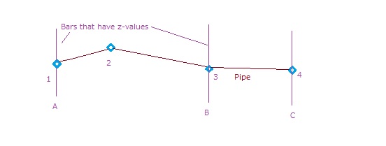
I have a sewage pipe that runs for several kilometers that is drawn as a 3Dpolyline, with correct x- and y-values. It doesn't have any z-values yet and these are what I want to obtain. I want the polyline to have continous z-values that changes along the polyline (not only in vertexes) so that a smooth profile can be drawn if wanted. I have data of measured actual z-values for approximately every 500 meters or so along the sewage pipe and these are currently drawn as 3Dpolylines of around 20 meters going perpendicular to the pipe (as in the picture). In other words there are bars with z-values crossing the pipe all along the stretch. Now, what I want to do is to somehow make the polyline that represent the pipe to get the hights from these perpendicular bars with the measured z-values. If I try to draw a new 3Dpolyline between two of the measured bars where the actual pipe is supposed to be, the end vertexes of the 3Dpolyline gets the z-values of the bars. However, the value inbetween the bars gets the Z-value 0. So, if I start a 3Dpoly on bar 1 then continue the pipe with another vertex, and then finish off at the second bar I will have 2 vertexes with the correct z-value but the middle vertex will be incorrect (0). How do I get the pipe to get the correct zvalues automatically iterated from the values on the crossing bars? Is this even possible to do? Should I create a surface from the bars first, and in that case how do I do that? If possible I don't only want the vertexes between bars to have iterated z-values, I also want the entire line to have a correct value.
I've attatched a crappy image made in paint (since I don't have Autocad on my home PC, only at the office). And just to make things even clearer I'll give an example. Let's say the pipe distance from 1 to 2 is 10 meters, the distance between 1 to 3 is 30 meters and the z-values of bar A and bar B is 10 and 25 respecitvely. So, when I draw a 3Dpolyline from 1 to 4, I want the vertex 2 to automatically get z-value 15 (since it's 1/3 on the way to B). In the same way, I would like for example the point on the pipe that is right in between 2 and 3 to have the z-value 20. I won't mind redoing the bars to for example singualar points instead, if that makes it all easier.
I'm really appreciating any help I can get with this! I get the feeling that it's easier than I belive it is to solve, and I feel that it should be possible. I just can't figure out how... =(
Sorry for the long description, I just wanted to make everything crystal clear 😃
Thanks!
23 REPLIES 23
Message 2 of 24
01-20-2013
07:42 AM
- Mark as New
- Bookmark
- Subscribe
- Mute
- Subscribe to RSS Feed
- Permalink
- Report
01-20-2013
07:42 AM
i don't have civil handy at the moment but you could create a surface from all the bars and then create a featureline taking levels from the surface just created. i assume that the bars have the correct z values.
AEC Collection 2024 UKIE (mainly Civil 3D UKIE and IW)
Win 11 Pro x64, 1Tb Primary SSD, 1Tb Secondary SSD
64Gb RAM Intel(R) Xeon(R) W-11855M CPU @ 3.2GHz
NVIDIA RTX A5000 16Gb, Dual 27" Monitor, Dell Inspiron 7760
neilyj (No connection with Autodesk other than using the products in the real world)
Did you find this post helpful? Feel free to Like this post.
Did your question get successfully answered? Then click on the ACCEPT SOLUTION button.
AEC Collection 2024 UKIE (mainly Civil 3D UKIE and IW)
Win 11 Pro x64, 1Tb Primary SSD, 1Tb Secondary SSD
64Gb RAM Intel(R) Xeon(R) W-11855M CPU @ 3.2GHz
NVIDIA RTX A5000 16Gb, Dual 27" Monitor, Dell Inspiron 7760
Message 3 of 24
01-20-2013
07:47 AM
- Mark as New
- Bookmark
- Subscribe
- Mute
- Subscribe to RSS Feed
- Permalink
- Report
01-20-2013
07:47 AM
Hi, thank you for your reply.
Yes, the bars have the right z-values, and creating a surface was my original thought too. But actually I haven't managed to create a surface sicne Autocad didn't want to recognize the bars as barriers. If creating a surface is the best way, some more info on exactly how to do it and what alternatives to use would be very welcome 😃
Message 4 of 24
01-20-2013
07:55 AM
- Mark as New
- Bookmark
- Subscribe
- Mute
- Subscribe to RSS Feed
- Permalink
- Report
01-20-2013
07:55 AM
create a new blank surface from your civil template, select all the bars and add to surface as breaklines, display triangles to ensure the surface has formed correctly.
Create a new featureline and grab the levels from the surface.
you may need to refer to help to achieve some of the above but at least you know what to look for, can't post screenshots as not at PC or laptop...
AEC Collection 2024 UKIE (mainly Civil 3D UKIE and IW)
Win 11 Pro x64, 1Tb Primary SSD, 1Tb Secondary SSD
64Gb RAM Intel(R) Xeon(R) W-11855M CPU @ 3.2GHz
NVIDIA RTX A5000 16Gb, Dual 27" Monitor, Dell Inspiron 7760
Create a new featureline and grab the levels from the surface.
you may need to refer to help to achieve some of the above but at least you know what to look for, can't post screenshots as not at PC or laptop...
neilyj (No connection with Autodesk other than using the products in the real world)
Did you find this post helpful? Feel free to Like this post.
Did your question get successfully answered? Then click on the ACCEPT SOLUTION button.
AEC Collection 2024 UKIE (mainly Civil 3D UKIE and IW)
Win 11 Pro x64, 1Tb Primary SSD, 1Tb Secondary SSD
64Gb RAM Intel(R) Xeon(R) W-11855M CPU @ 3.2GHz
NVIDIA RTX A5000 16Gb, Dual 27" Monitor, Dell Inspiron 7760
Message 5 of 24
01-20-2013
08:01 AM
- Mark as New
- Bookmark
- Subscribe
- Mute
- Subscribe to RSS Feed
- Permalink
- Report
01-20-2013
08:01 AM
Thank you for your reply! I quickly tried the same thing last week at work, but somehow when I tried to choose breaklines and pick the bars, "no selection" or something like that was written in the dialouge field. It's like cad didn't want to acknowledge that they are there or are good candidates for breaklines. Do the bars have to have any certain properties? It should work with 3D polylines, right? Maybe I will have to try this all over again at work tomorrow, I wonder what I missed...
Message 6 of 24
01-20-2013
08:05 AM
- Mark as New
- Bookmark
- Subscribe
- Mute
- Subscribe to RSS Feed
- Permalink
- Report
01-20-2013
08:05 AM
shouldn't be a problem based on your description, are you able to post the drawing as this will allow myself or someone else to see exactly what may be the problem?
AEC Collection 2024 UKIE (mainly Civil 3D UKIE and IW)
Win 11 Pro x64, 1Tb Primary SSD, 1Tb Secondary SSD
64Gb RAM Intel(R) Xeon(R) W-11855M CPU @ 3.2GHz
NVIDIA RTX A5000 16Gb, Dual 27" Monitor, Dell Inspiron 7760
neilyj (No connection with Autodesk other than using the products in the real world)
Did you find this post helpful? Feel free to Like this post.
Did your question get successfully answered? Then click on the ACCEPT SOLUTION button.
AEC Collection 2024 UKIE (mainly Civil 3D UKIE and IW)
Win 11 Pro x64, 1Tb Primary SSD, 1Tb Secondary SSD
64Gb RAM Intel(R) Xeon(R) W-11855M CPU @ 3.2GHz
NVIDIA RTX A5000 16Gb, Dual 27" Monitor, Dell Inspiron 7760
Message 7 of 24
01-20-2013
08:09 AM
- Mark as New
- Bookmark
- Subscribe
- Mute
- Subscribe to RSS Feed
- Permalink
- Report
01-20-2013
08:09 AM
I can post a part of the drawing tomorrow when I get to work. I will try the to create the surface again as described aswell and see what happens. And if it doesn't work, I'll post a picture here. Thank you for your help 😃
Message 8 of 24
01-20-2013
08:11 AM
- Mark as New
- Bookmark
- Subscribe
- Mute
- Subscribe to RSS Feed
- Permalink
- Report
01-20-2013
08:11 AM
no worries , btw what version of civil are you running?
AEC Collection 2024 UKIE (mainly Civil 3D UKIE and IW)
Win 11 Pro x64, 1Tb Primary SSD, 1Tb Secondary SSD
64Gb RAM Intel(R) Xeon(R) W-11855M CPU @ 3.2GHz
NVIDIA RTX A5000 16Gb, Dual 27" Monitor, Dell Inspiron 7760
neilyj (No connection with Autodesk other than using the products in the real world)
Did you find this post helpful? Feel free to Like this post.
Did your question get successfully answered? Then click on the ACCEPT SOLUTION button.
AEC Collection 2024 UKIE (mainly Civil 3D UKIE and IW)
Win 11 Pro x64, 1Tb Primary SSD, 1Tb Secondary SSD
64Gb RAM Intel(R) Xeon(R) W-11855M CPU @ 3.2GHz
NVIDIA RTX A5000 16Gb, Dual 27" Monitor, Dell Inspiron 7760
Message 9 of 24
01-20-2013
09:54 AM
- Mark as New
- Bookmark
- Subscribe
- Mute
- Subscribe to RSS Feed
- Permalink
- Report
01-20-2013
09:54 AM
You can use the surface to get the elevations of the pipes at the locations of your lines but that won't necessarily give you the correct elevation at the pipes themselves.
Watch THIS to see what I'm referring to.
Message 10 of 24
01-20-2013
10:49 AM
- Mark as New
- Bookmark
- Subscribe
- Mute
- Subscribe to RSS Feed
- Permalink
- Report
01-20-2013
10:49 AM
Oh my thank you so much for taking the time making that awesome video! And the solution using points instead of lines for the z-levels will give the correct result now that I think about it - thank you so much for explaining that and how to create the surface to me! Just so you know you've been of great help in figuring out details for modeling the sewer system in Stockholm, Sweden 😃
Thanks! ❤️
Message 11 of 24
01-20-2013
11:25 AM
- Mark as New
- Bookmark
- Subscribe
- Mute
- Subscribe to RSS Feed
- Permalink
- Report
01-20-2013
11:25 AM
Nice video Brian - never seen Project Chronicle in use before
neilyj (No connection with Autodesk other than using the products in the real world)
Did you find this post helpful? Feel free to Like this post.
Did your question get successfully answered? Then click on the ACCEPT SOLUTION button.
AEC Collection 2024 UKIE (mainly Civil 3D UKIE and IW)
Win 11 Pro x64, 1Tb Primary SSD, 1Tb Secondary SSD
64Gb RAM Intel(R) Xeon(R) W-11855M CPU @ 3.2GHz
NVIDIA RTX A5000 16Gb, Dual 27" Monitor, Dell Inspiron 7760
Message 12 of 24
01-20-2013
03:19 PM
- Mark as New
- Bookmark
- Subscribe
- Mute
- Subscribe to RSS Feed
- Permalink
- Report
01-20-2013
03:19 PM
@neilyj666 wrote:Nice video Brian - never seen Project Chronicle in use before
I'm liking it more and more. It's great for helping out with the actual program as it records commands and dialog boxes and well as mouse clicks. In this case, the sound didn't turn out all that great because I was just using the microphone on my laptop. If I was trying to do something a bit more professional, I would have used a head set.
For anyone not aware of it, it's a lab tool so it MIGHT not be available in the future. Some of the lab functions have been made a part of Autodesk 360 so it might require cloud units in the future to use it (if it goes that way). All of this speculation is just that. 100% pure speculation. If I had any idea where this software was going, I wouldn't say.
Remember the old saying, "Those that say, don't know. Those that know, don't say." (That is, with regards to what Autodesk is doing in the future.)
Message 13 of 24
01-20-2013
06:28 PM
- Mark as New
- Bookmark
- Subscribe
- Mute
- Subscribe to RSS Feed
- Permalink
- Report
01-20-2013
06:28 PM
It's nice though I wish one could edit the videos ala Camtasia after recording.
Matt Kolberg
SolidCAD Professional Services
http://www.solidcad.ca /

SolidCAD Professional Services
http://www.solidcad.ca /
Message 14 of 24
01-20-2013
07:25 PM
- Mark as New
- Bookmark
- Subscribe
- Mute
- Subscribe to RSS Feed
- Permalink
- Report
01-20-2013
07:25 PM
@mathewkol wrote:
It's nice though I wish one could edit the videos ala Camtasia after recording.
I agree. Just remember this is still in "labs" so we may yet get that ability. If nothing else, the ability to trim off the beginning and end so they don't have to see me fumbling around as I start and end the video.
Message 15 of 24
01-21-2013
03:56 AM
- Mark as New
- Bookmark
- Subscribe
- Mute
- Subscribe to RSS Feed
- Permalink
- Report
01-21-2013
03:56 AM
So, arriving at work this morning I was eager to try to create a surface and create feature line with correct elevations. However, of some reason I'm unable to add the bars as Breaklines. I follow your instruction video step by step, but when I select the bars, right click on Breaklines --> Add and press OK (type=standard) nothing what so ever happens! I can't do it the other way around either by right clicking first, clicking Add and OK and then selecting the bars. No plus appears infront of the breakline and no grid is created. When I do the latter way and try to select the bars the command field saýs "Select objects: 1 found, 3 total", when I try selecting 3 for example. It's as if they aren't valid. What can be the problem here? Why can't I add the bars as breaklines? I tried to convert the bars from just lines with elevations into 3Dpolylines, but that didn't help either. The only thing I can see that is different from what I'm doing and what Brian showed in the video, is that my Surface, Surface1 does't have a small yellow triangle over the icon. Also, there are fewer elements under the Definition tab. Does that change anything or give any hints as to what's going on?
I attached a screen shot.
Message 16 of 24
01-21-2013
04:03 AM
- Mark as New
- Bookmark
- Subscribe
- Mute
- Subscribe to RSS Feed
- Permalink
- Report
01-21-2013
04:03 AM
Can you post some data?
neilyj (No connection with Autodesk other than using the products in the real world)
Did you find this post helpful? Feel free to Like this post.
Did your question get successfully answered? Then click on the ACCEPT SOLUTION button.
AEC Collection 2024 UKIE (mainly Civil 3D UKIE and IW)
Win 11 Pro x64, 1Tb Primary SSD, 1Tb Secondary SSD
64Gb RAM Intel(R) Xeon(R) W-11855M CPU @ 3.2GHz
NVIDIA RTX A5000 16Gb, Dual 27" Monitor, Dell Inspiron 7760
Message 17 of 24
01-21-2013
07:24 AM
- Mark as New
- Bookmark
- Subscribe
- Mute
- Subscribe to RSS Feed
- Permalink
- Report
01-21-2013
07:24 AM
Specificly what data would you need?
I'm quite in the learning phase here, and I can't post too much information about the obejct I'm working with so guidance would be good =(
Message 18 of 24
01-21-2013
07:32 AM
- Mark as New
- Bookmark
- Subscribe
- Mute
- Subscribe to RSS Feed
- Permalink
- Report
01-21-2013
07:32 AM
specifically the bars that can't be added to a surface (select about 6, isolate, wblock to a new dwg and post)
neilyj (No connection with Autodesk other than using the products in the real world)
Did you find this post helpful? Feel free to Like this post.
Did your question get successfully answered? Then click on the ACCEPT SOLUTION button.
AEC Collection 2024 UKIE (mainly Civil 3D UKIE and IW)
Win 11 Pro x64, 1Tb Primary SSD, 1Tb Secondary SSD
64Gb RAM Intel(R) Xeon(R) W-11855M CPU @ 3.2GHz
NVIDIA RTX A5000 16Gb, Dual 27" Monitor, Dell Inspiron 7760
Message 19 of 24
01-21-2013
10:01 AM
- Mark as New
- Bookmark
- Subscribe
- Mute
- Subscribe to RSS Feed
- Permalink
- Report
01-21-2013
10:01 AM
List one of the "bars" and let us know what type of object it is. If it's a block, you can't add it as a breakline.
Message 20 of 24
01-22-2013
12:35 AM
- Mark as New
- Bookmark
- Subscribe
- Mute
- Subscribe to RSS Feed
- Permalink
- Report
01-22-2013
12:35 AM
They are regular lines. I posted an attatchment jpeg in the last post where the properties for the bars can be seen.
Reply
Topic Options
- Subscribe to RSS Feed
- Mark Topic as New
- Mark Topic as Read
- Float this Topic for Current User
- Bookmark
- Subscribe
- Printer Friendly Page

