Community
- Forums Home
- >
- Civil 3D Community
- >
- Civil 3D Forum
- >
- How to apply my centerline profile to my 2d river
Civil 3D Forum
Welcome to Autodesk’s Civil 3D Forums. Share your knowledge, ask questions, and explore popular AutoCAD Civil 3D topics.
Turn on suggestions
Auto-suggest helps you quickly narrow down your search results by suggesting possible matches as you type.
Reply
Topic Options
- Subscribe to RSS Feed
- Mark Topic as New
- Mark Topic as Read
- Float this Topic for Current User
- Bookmark
- Subscribe
- Printer Friendly Page
Message 1 of 19
Anonymous
1176 Views, 18 Replies
05-11-2012
05:21 PM
- Mark as New
- Bookmark
- Subscribe
- Mute
- Subscribe to RSS Feed
- Permalink
- Report
05-11-2012
05:21 PM
How to apply my centerline profile to my 2d river
Hi, I created a 2d drawing of a river I am building and constructed a centerline. I already have a surface of the existing ground created from which i created an alignment of the centerline and created a profile showing the existing grade along the centerline. Then I created another alignment on the same profile which shows the bottom of my river that I want. I now want to calculate the cut and fill of my project but don't know how. Is there a way I can create a surface of my river from my profile? Or what process do I follow to apply my centerline profile to my 2d river. I am stuck and need some guidance. Thanks, Grant
18 REPLIES 18
Message 2 of 19
05-11-2012
06:21 PM
- Mark as New
- Bookmark
- Subscribe
- Mute
- Subscribe to RSS Feed
- Permalink
- Report
05-11-2012
06:21 PM
You will need to create an assembly (typical cross sevtion) then a corridor.
There are tutorials for each of these in help.
There are tutorials for each of these in help.
Matt Kolberg
SolidCAD Professional Services
http://www.solidcad.ca /

SolidCAD Professional Services
http://www.solidcad.ca /
Message 3 of 19
Anonymous
in reply to:
Anonymous
05-12-2012
05:10 AM
- Mark as New
- Bookmark
- Subscribe
- Mute
- Subscribe to RSS Feed
- Permalink
- Report
05-12-2012
05:10 AM
If you are working with a natural channel, or are creating a new channel with a "natural" shape, assembly's and corridors don't help too much. Unfortunately the alternative - working with feature lines - is very unstable (version 13 seems even worse), but it is the only way we have been able to represent the channel, carry out hydraulic analysis, do cut & fill, etc. We have lost loads of hours trying to make minor adjustments to the river channel.
Civil 3D has proved to be a real dog for river work. Good luck...
Message 4 of 19
05-12-2012
10:07 AM
- Mark as New
- Bookmark
- Subscribe
- Mute
- Subscribe to RSS Feed
- Permalink
- Report
05-12-2012
10:07 AM
If my river is irregular shape how will I be able to create an assembly and then a corridor to accurately represent my river? I search for several hours for a tutorial that would help me and I have not found any. The only tuturials I found was for roads.
Message 5 of 19
Anonymous
in reply to:
Anonymous
05-12-2012
10:12 AM
- Mark as New
- Bookmark
- Subscribe
- Mute
- Subscribe to RSS Feed
- Permalink
- Report
05-12-2012
10:12 AM
Thanks stuart-D
What do you mean by working with feature lines? Were you able to make a 3d model of your river? I was able to calaulate the amount of cut of my river only by creating a profile of the existing gournd CL and plotting my grade on the same profile. Then I calculated the area between the two and times it by my average width of my river. This sounds basic but I can't figure out any other way with the irregular shaped river. Anymore suggestions would really help.
Thanks,
Message 6 of 19
05-12-2012
11:59 AM
- Mark as New
- Bookmark
- Subscribe
- Mute
- Subscribe to RSS Feed
- Permalink
- Report
05-12-2012
11:59 AM
How you deal with corridors and assemlies depends on the nature of the irregular shape. Attach a sketch.
Matt Kolberg
SolidCAD Professional Services
http://www.solidcad.ca /
SolidCAD Professional Services
http://www.solidcad.ca /
Message 7 of 19
Anonymous
in reply to:
Anonymous
05-13-2012
05:27 AM
- Mark as New
- Bookmark
- Subscribe
- Mute
- Subscribe to RSS Feed
- Permalink
- Report
05-13-2012
05:27 AM
The solution I can see is to separate your river survey into two portions - a river bottom survey and a top of water survey, create two surfaces and then difference/compare them to get volumes.
Message 8 of 19
Anonymous
in reply to:
Anonymous
05-13-2012
06:34 AM
- Mark as New
- Bookmark
- Subscribe
- Mute
- Subscribe to RSS Feed
- Permalink
- Report
05-13-2012
06:34 AM
Hi Grant,
Yes we did get a 3-D model of the river. You define a set of sample lines along the CL and from those you can extract sections for hydraulic analysis (or import directly into HEC-Ras), and you can also do the volume calculations. If you are looking at cut and fill you will need a separate surface for your new engineered surface. Then the cut and fill volumes are calculated between the sample lines by the software. The latter is fairly straight forward - it's defining the new surface where you need feature lines to define the new channel shape. This is what's long and tedious as it is very unstable.
I note a later comment that implies that assemblies can still be used to describe natural channel sections. From our investigations we understand you need to draw an assembly for every section as they will all be different. If you are dealing with river lengths of some distance, this will be exceedingly tedious - especially if you have design changes. Using feature lines initially seemed to be the answer, but software stability is a problem as I have said.
Also be aware the 3-D surface you see in the object viewer is not necessarily what appears in your sample lines, so you need to check them all for triangulation discrepancies.
E-mail me on stuart@fourthelement.co.za and I will get you someone to give you the details about using feature lines. We also know there are a few others out there with more experience of this than ours, especially in the US, but they confirmed we seemed to be on the right track. Hopefully AutoDesk will get round to sorting out the stability issues soon.
Regards, stuart
Message 9 of 19
05-13-2012
07:24 AM
- Mark as New
- Bookmark
- Subscribe
- Mute
- Subscribe to RSS Feed
- Permalink
- Report
05-13-2012
07:24 AM
I really can't imagine requiring a different assemvly for each section. Maybe, though I can't say without seeing the design.
Matt Kolberg
SolidCAD Professional Services
http://www.solidcad.ca /
SolidCAD Professional Services
http://www.solidcad.ca /
Message 10 of 19
05-13-2012
02:25 PM
- Mark as New
- Bookmark
- Subscribe
- Mute
- Subscribe to RSS Feed
- Permalink
- Report
05-13-2012
02:25 PM
A river channel section is more organic than a normal corridor section, with changes in width and slopes at every section. I would think that it's possible to have an assembly with enough flexibility built in so that it could be controlled with a series of offset alignments and profiles to produce a natural looking channel. Post a drawing with some existing and proposed sections so that we can see exactly what you're trying to achieve.
Steve
Expert Elite Alumnus
Expert Elite Alumnus
Message 11 of 19
05-13-2012
04:25 PM
- Mark as New
- Bookmark
- Subscribe
- Mute
- Subscribe to RSS Feed
- Permalink
- Report
05-13-2012
04:25 PM
A few handy links I found/remembered:
http://bimontherocks.typepad.com/my_weblog/2009/03/civil-3d-success-stories-stream-restoration.html (follow the links in there)
http://bimontherocks.typepad.com/my_weblog/2009/10/leveraging-a-temporary-corridor-for-stream-projec... (great post!)
There are other posts on Dana's blog too - have a search round for them.
http://labs.autodesk.com/utilities/civil3d_river/
Also there is this - haven't used it myself but, and it is a Labs add-on so please read the condtiions of use.
Message 12 of 19
05-13-2012
05:07 PM
- Mark as New
- Bookmark
- Subscribe
- Mute
- Subscribe to RSS Feed
- Permalink
- Report
05-13-2012
05:07 PM
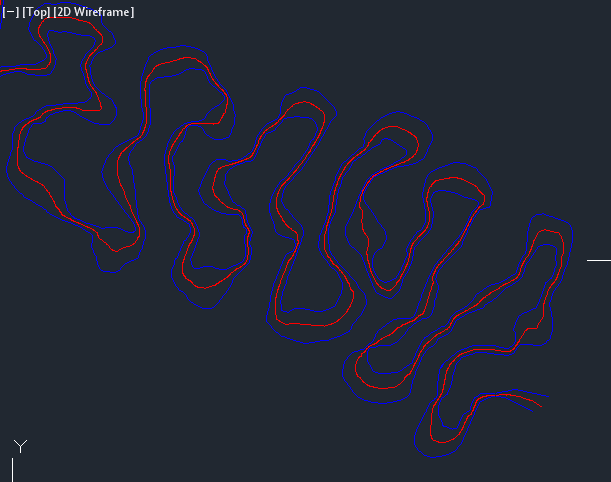
I have attached a graphic of my proposed river with centreline. I have the river profile done for the centreline but as previously stated I do not know how to create a surface or 3d model of my river with only a cl profile. Now that you can see my river and how irregular shape it is do you think creating numerous sections and assemby's will help create what I am looking for. If there was a way I could apply the cl profile values to my entire river would be great but I am sure there is no easy way to do this.
Thanks for all the suggestions
Message 14 of 19
Anonymous
in reply to:
Anonymous
07-16-2012
01:38 PM
- Mark as New
- Bookmark
- Subscribe
- Mute
- Subscribe to RSS Feed
- Permalink
- Report
07-16-2012
01:38 PM
Do you need something like this? (Skip to time 1:00 specifically)
http://www.youtube.com/watch?v=e2AG4c3WhP0
Drafting a 3D stream is extremely complicated and I can tell you feature lines are the best method by far. PM me if you have more specific questions on how to do this.
Mike
Message 15 of 19
Anonymous
in reply to:
Anonymous
07-17-2012
05:36 AM
- Mark as New
- Bookmark
- Subscribe
- Mute
- Subscribe to RSS Feed
- Permalink
- Report
07-17-2012
05:36 AM
Mike, if you were kind enough to share your method with the group, I for one would certainly appreciate it...
Regards
- Mick
Message 16 of 19
Anonymous
in reply to:
Anonymous
07-17-2012
06:42 AM
- Mark as New
- Bookmark
- Subscribe
- Mute
- Subscribe to RSS Feed
- Permalink
- Report
07-17-2012
06:42 AM
Just a thought: what about simply drawing your river bed contour lines (either by hand or by offsets), assigning some elevations then creating a surface from these contours? Your river form could be as organic as required and it would be very quick. Cheers - Mick
Message 17 of 19
Anonymous
in reply to:
Anonymous
07-17-2012
07:05 AM
- Mark as New
- Bookmark
- Subscribe
- Mute
- Subscribe to RSS Feed
- Permalink
- Report
07-17-2012
07:05 AM
Mike,
Thanks for the YouTube clip. Like you we resorted to using feature lines which were not only better for describing the natural river bed but also in design of the rehabilitated channel. But a point I made at the start of this discussion was around my frustration with the stability of Civil 3D using this approach. As I said before we lost many hours and missed a deadline trying to get the systems to function. It all seemed to start going wrong when we applied the feature lines to the 3D surface and then started manipulating the channel section for the new hydraulic design. If you have a secret to getting around this problem, it would be great to hear it.
We have reverted back to Version 2012 as it seems more stable, and have had our hardware checked out, so we are sure that's not the problem.
stuart
Message 18 of 19
07-17-2012
07:34 AM
- Mark as New
- Bookmark
- Subscribe
- Mute
- Subscribe to RSS Feed
- Permalink
- Report
07-17-2012
07:34 AM
I've been using featurelines in 2013 on a few projects, and have not seen any problems like you describe. I am currently only using feature lines for surface breaklines.
Stuart - were you using them with grading objects or just to build surfaces?
Steve
Expert Elite Alumnus
Expert Elite Alumnus
Message 19 of 19
07-17-2012
09:37 AM
- Mark as New
- Bookmark
- Subscribe
- Mute
- Subscribe to RSS Feed
- Permalink
- Report
07-17-2012
09:37 AM
We have spent many years developing a process that really works for us and my company is actually offering to train others on this process. I don’t want to leave you in the dark completely with that so I will say, the most stable method that we have found to use for stream design is a combination of alignments, profiles, and feature lines used as surface breaklines.
I’m sure we’re all aware that actually creating a good design within the geomorphic parameters is quite daunting. However, we have some great tools that help us get our intended design into Civil3D and ultimately constructed the way we envisioned. These tools include spreadsheets and a number of custom styles and parts in Civil3D.
If you are interested in the training we offer, please give me a call. I would love to help make the Civil3D part of the design less of a headache for you.
Mike Aust
(804) 200-6447
Timmons Group
Reply
Topic Options
- Subscribe to RSS Feed
- Mark Topic as New
- Mark Topic as Read
- Float this Topic for Current User
- Bookmark
- Subscribe
- Printer Friendly Page
Forums Links
Can't find what you're looking for? Ask the community or share your knowledge.
Post to forums

