Community
Civil 3D Forum
Welcome to Autodesk’s Civil 3D Forums. Share your knowledge, ask questions, and explore popular AutoCAD Civil 3D topics.
Turn on suggestions
Auto-suggest helps you quickly narrow down your search results by suggesting possible matches as you type.
Reply
Topic Options
- Subscribe to RSS Feed
- Mark Topic as New
- Mark Topic as Read
- Float this Topic for Current User
- Bookmark
- Subscribe
- Printer Friendly Page
Message 1 of 16
Anonymous
9014 Views, 15 Replies
10-12-2012
01:13 AM
- Mark as New
- Bookmark
- Subscribe
- Mute
- Subscribe to RSS Feed
- Permalink
- Report
10-12-2012
01:13 AM
Corridor - Right angle corner / Bowtie
Hi
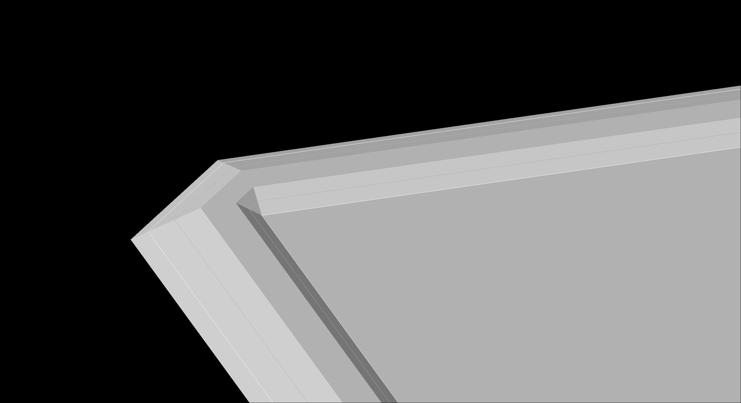
I have a Corridor issue - does anyone know how to fix the inside / outside corners of right angle corridor?
Im doing a embankment lift and the client wants the corners neatly and not curved or champers.
We often get a problem like, so help would be very nice! Also the outside corner should not curve. I can do it with gradings or futurelines, but if there is a design change i have to redo everything.
See the assembly - this is only the first lift.
Thanks
Riaan
15 REPLIES 15
Message 3 of 16
10-13-2012
09:51 AM
- Mark as New
- Bookmark
- Subscribe
- Mute
- Subscribe to RSS Feed
- Permalink
- Report
10-13-2012
09:51 AM
Assuming that your alignment is at the inside of the berm the solution here is to add a very small radius curve at the corner, then add a single corridor section at the midpoint of that curve. You will have to use the corridor section view/editor to adjust the assembly parameters for this new section.
Steve
Expert Elite Alumnus
Expert Elite Alumnus
Message 4 of 16
10-13-2012
02:34 PM
- Mark as New
- Bookmark
- Subscribe
- Mute
- Subscribe to RSS Feed
- Permalink
- Report
10-13-2012
02:34 PM
@Anonymous wrote:Hi
I have a Corridor issue - does anyone know how to fix the inside / outside corners of right angle corridor?
Im doing a embankment lift and the client wants the corners neatly and not curved or champers.
We often get a problem like, so help would be very nice! Also the outside corner should not curve. I can do it with gradings or futurelines, but if there is a design change i have to redo everything.
See the assembly - this is only the first lift.
Thanks
Riaan
So what kind of corner do you want?
Joe Bouza
Did you find this post helpful? Feel free to Like this post.
Did your question get successfully answered? Then click on the ACCEPT SOLUTION button.
Message 5 of 16
10-14-2012
01:18 AM
- Mark as New
- Bookmark
- Subscribe
- Mute
- Subscribe to RSS Feed
- Permalink
- Report
10-14-2012
01:18 AM
I think Riann wants the corners to be sharp corners with no chamfers or roundings.
As steve said, a very small arc with a frequency station at the centre.
Here is a step by step post
http://andrewscivil3dstuff.blogspot.com.au/2011/06/create-corridor-with-90-degree-bend.html
If a post provides a fix for your issue, click on "Accept as Solution" to help other users find solutions to problems they might have that are similar to yours.
Andrew Puller
Maitland, NSW, Australia
Windows 10 Enterprise 64bit
Intel core i7 11800 @ 2.30 GHz with 32GB Ram
Civil 3d 2023
Message 6 of 16
10-14-2012
06:50 PM
- Mark as New
- Bookmark
- Subscribe
- Mute
- Subscribe to RSS Feed
- Permalink
- Report
10-14-2012
06:50 PM
hi Andrew
thanks for the blog - iv tried that before but does not quite work. It works well when the surface is close to the ground, but the higher you go, the more complicated it gets.
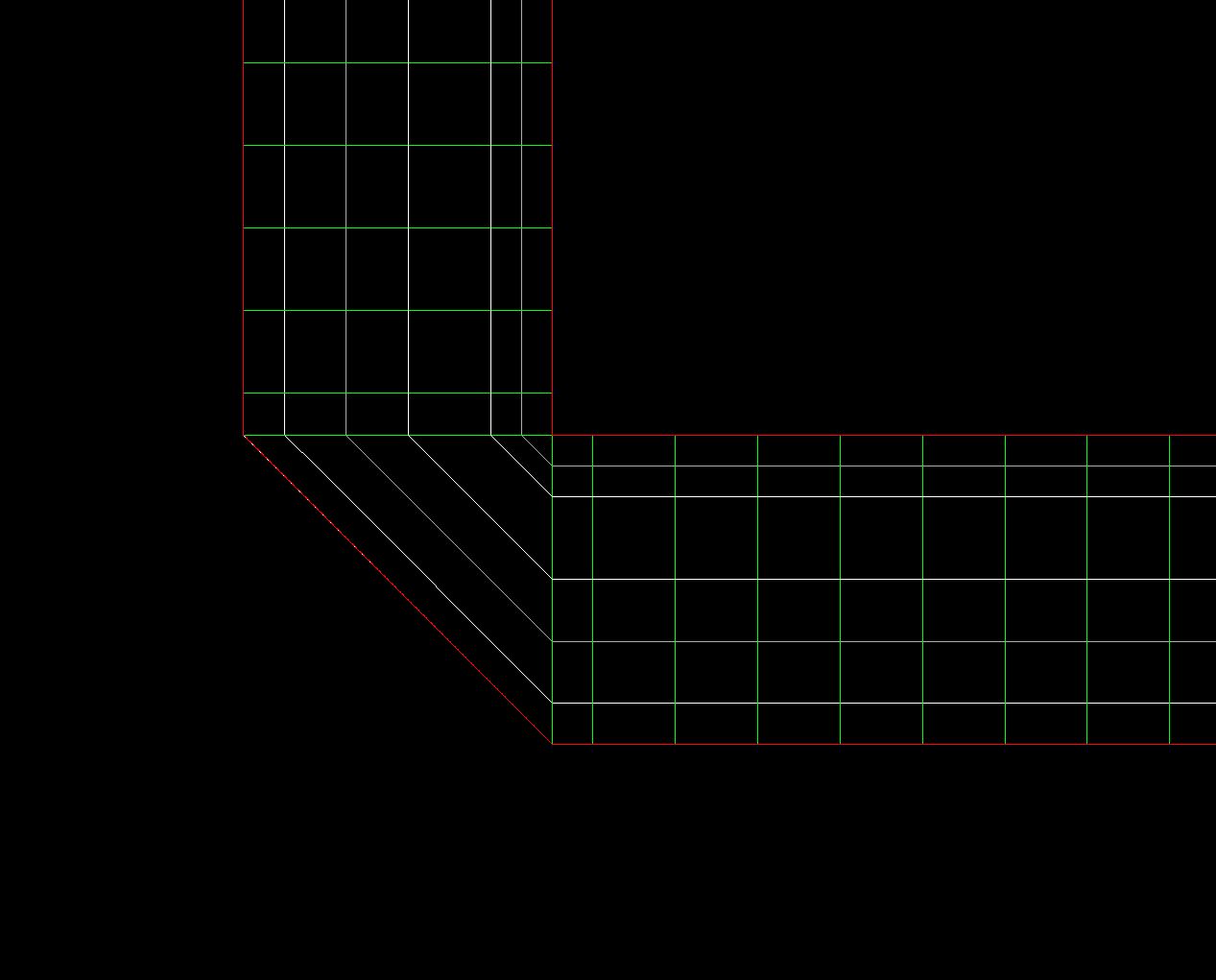
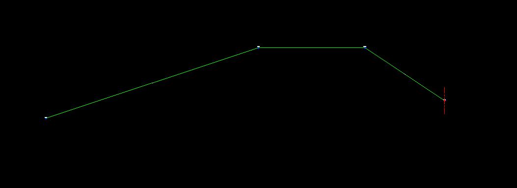
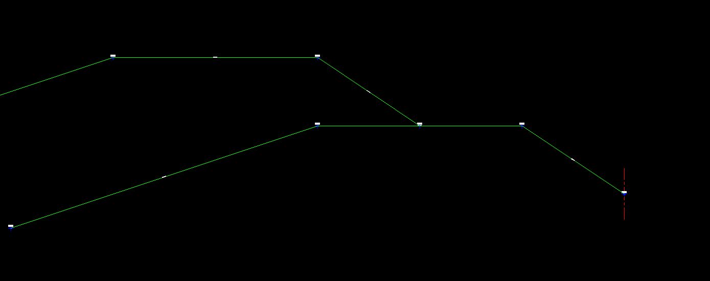
Iv attached two more pics, second try at the corridor.
The client wants a sharp outside / inside corner. I've tried the small radius, but as the lifts / raises progress, the bigger the arc gets on the outside.
The alignment starts fro the inside going outwards, I've also tried going from the outside going in, but then I end up with a bowtie effect.
This would be easier with offset polylines or gradings but there must be solution for this issue.
I still need to go up 10 lifts / raise, so the arc is going to be massive at the end.
Thanks
Riaan
Civil 3D
Intel(R) Xeon(R) CPU
X5675 @3.07GHz
64-bit
24GB RAM
Message 7 of 16
10-14-2012
07:40 PM
- Mark as New
- Bookmark
- Subscribe
- Mute
- Subscribe to RSS Feed
- Permalink
- Report
10-14-2012
07:40 PM
You will need to have an alignment to target for the outside that does not have an arc in it.
Offset your base alignment outward using the standard autocad offset command and then fillet the corner/s of the polyline with zero radius to remove the arcs. Create an alignment from polyline and use that as your outside target.
If a post provides a fix for your issue, click on "Accept as Solution" to help other users find solutions to problems they might have that are similar to yours.
Andrew Puller
Maitland, NSW, Australia
Windows 10 Enterprise 64bit
Intel core i7 11800 @ 2.30 GHz with 32GB Ram
Civil 3d 2023
Message 8 of 16
10-15-2012
12:23 AM
- Mark as New
- Bookmark
- Subscribe
- Mute
- Subscribe to RSS Feed
- Permalink
- Report
10-15-2012
12:23 AM
You have encounted a fundamental weakness in Civil 3D: it cannot dynamically model projected mitered corners. You can't do it with with corridors, offset alignments or gradings. The best you can do is minimize the fillet or chamfer by getting as close as you can to the final solution with featurelines or alignments and using them as corridor targets or for gradings.
Neil Wilson (a.k.a. neilw)
AEC Collection/C3D 2024, LDT 2004, Power Civil v8i SS1
WIN 10 64 PRO
http://www.sec-landmgt.com
AEC Collection/C3D 2024, LDT 2004, Power Civil v8i SS1
WIN 10 64 PRO
http://www.sec-landmgt.com
Message 9 of 16
12-06-2017
01:20 PM
- Mark as New
- Bookmark
- Subscribe
- Mute
- Subscribe to RSS Feed
- Permalink
- Report
12-06-2017
01:20 PM
I agree with @Neilw_05.
Regardless of anything Autodesk might tells us, the Corridor Workflow is only intended for designing roadways with gentle curves. After all these are high speed roadways.
Any use beyond roadway design is outside the anticipated work flow and will require workarounds and compromises.
As suggested, I have used fillets as small as 0.001 ft. This means that using the fillet radius point is still accurate enough for construction layout. Working from outside in might help. Bowtie cleanup does not work variable width (targeted) subassemblies, so you may need to use multiple baselines.
Corridors are smarter than and a much more complete grading solutions than Feature Line grading and Grading Objects. Corridors can create a model with multiple materials, datum, surfaces etc. that can be used for quantity calculations. (This is as close as Civil 3D comes to BIM.)
Feature line grading and grading objects only provide simple surfaces.
Feature Line grading is tedious not dynamic.
Grading objects are dynamic, but seem to have a limited lifetime. (Blink and they are gone) Experienced users suggest detaching grading group surfaces and/or exploding grading objects and using the remaining feature line, before the grading objects corrupt the drawing and become unstable. Grading Objects are not a Civil 3D Point of Pride.
State Department of Transportation (DOT) adoption of Civil 3D seems to be major desire of Autodesk. This may bode well for those of us interested in Corridor improvement. Unfortunately, the DOTs work pretty much exclusively with roadways and gentle curves; DOTs are unlikely to drive the enhancements we want ,but we can always hope.
Christopher Stevens
Did you find this post helpful? Feel free to Like this post.
Did your question get successfully answered? Then click on the ACCEPT SOLUTION button.
Message 10 of 16
12-06-2017
03:22 PM
- Mark as New
- Bookmark
- Subscribe
- Mute
- Subscribe to RSS Feed
- Permalink
- Report
12-06-2017
03:22 PM
The sharp corners should be possible by treating each corner as an intersection, with the horizontal target being a line bisecting the corner. Vertical targeting shouldn't be needed.
Message 11 of 16
12-06-2017
11:20 PM
- Mark as New
- Bookmark
- Subscribe
- Mute
- Subscribe to RSS Feed
- Permalink
- Report
12-06-2017
11:20 PM
@Anonymous, you might want to look at @sboons comment.
Adding an arc and single section at the center of the arc may be the first step to your solution.
As @sboon says you then need to edit the properties of that section. Your subassembly needs to have input parameters Berm-Inside-Slope, Berm-Top and Daylight-Slope. For a 90 degree corner, the bisector is at 45 degrees. Lengths along the bisector are 1.414 (See note 1.) times lengths perpendicular to the berm.
If the normal Berm-Inside-Slope is 2:1, edit the bisector section Berm-Inside-Slope to be 2.828:1
If the normal Berm-Top is 10 ft, edit the bisector section Berm-Top to be 14.14 ft
If the normal Daylight-Slope is 4:1, edit the bisector section Daylight-Slope to be 5.636:1
Editing the bisector section eliminates the chamfer. The edited parameters force the computed points to fall on the desired miter. Since there is only one section in the curve, the "arc" is tessellates as 2 straight lines. (See note 2.)
Notes:
- A 45 degree miter results in a factor of 1 Horizontal, 1 vertical, Sqrt(2)=1.414 Diagonal. The factor will be different for other than a 90 degree corner.
- As you build outward, the curve becomes bigger. Make sure that the sample spacing along curves is long enough that you do not get extra sections in the curve area.
- This is a workaround, not a workflow. It is a kluge at best. Having to resort to this for a program as mature and expensive as Civil 3d is not reasonable. Autodesk should show some pride and fit this. I know that "programing is hard", but that is why the are paid the big bucks.
Christopher Stevens
Did you find this post helpful? Feel free to Like this post.
Did your question get successfully answered? Then click on the ACCEPT SOLUTION button.
Message 12 of 16
12-06-2017
11:23 PM
- Mark as New
- Bookmark
- Subscribe
- Mute
- Subscribe to RSS Feed
- Permalink
- Report
Message 14 of 16
12-07-2017
09:37 AM
- Mark as New
- Bookmark
- Subscribe
- Mute
- Subscribe to RSS Feed
- Permalink
- Report
12-07-2017
09:37 AM
@Anonymous, thanks for the very prompt reply! I will look this over later today.
Christopher Stevens
Did you find this post helpful? Feel free to Like this post.
Did your question get successfully answered? Then click on the ACCEPT SOLUTION button.
Message 15 of 16
12-07-2017
09:59 AM
- Mark as New
- Bookmark
- Subscribe
- Mute
- Subscribe to RSS Feed
- Permalink
- Report
12-07-2017
09:59 AM
I find the amount of work required to model mitered corners with corridors is excessive. Imagine doing this on a site with perhaps 100 corners!
Neil Wilson (a.k.a. neilw)
AEC Collection/C3D 2024, LDT 2004, Power Civil v8i SS1
WIN 10 64 PRO
http://www.sec-landmgt.com
AEC Collection/C3D 2024, LDT 2004, Power Civil v8i SS1
WIN 10 64 PRO
http://www.sec-landmgt.com
Message 16 of 16
06-30-2021
05:33 AM
- Mark as New
- Bookmark
- Subscribe
- Mute
- Subscribe to RSS Feed
- Permalink
- Report
Reply
Topic Options
- Subscribe to RSS Feed
- Mark Topic as New
- Mark Topic as Read
- Float this Topic for Current User
- Bookmark
- Subscribe
- Printer Friendly Page
Forums Links
Can't find what you're looking for? Ask the community or share your knowledge.
Post to forums

