Community
Civil 3D Forum
Welcome to Autodesk’s Civil 3D Forums. Share your knowledge, ask questions, and explore popular AutoCAD Civil 3D topics.
Turn on suggestions
Auto-suggest helps you quickly narrow down your search results by suggesting possible matches as you type.
Reply
Topic Options
- Subscribe to RSS Feed
- Mark Topic as New
- Mark Topic as Read
- Float this Topic for Current User
- Bookmark
- Subscribe
- Printer Friendly Page
Message 1 of 17
09-01-2011
06:01 AM
- Mark as New
- Bookmark
- Subscribe
- Mute
- Subscribe to RSS Feed
- Permalink
- Report
09-01-2011
06:01 AM
I have a basic common Corridor modeling problem that I just can't seem to get past. So I am asking for help here.
I am working with a roadway section, right side only. On the right of this assembly, we have 12' lane at 2% cross-slope and 6% longitudinal grade, then 3' min wide shoulder at minimum cross slope 5% and max cross slope at 3:1, then a 10' bike path with 2% cross slope but a 5% longitudinal grade, then regular daylighting.
As the stationing increases, the bike path begins to diverge away from the road lane when the 3:1 max. threshold is reached for the 3' shoulder. The 3' shoulder begins to then increase in width to hold the 3:1 slope after this. To complicate things just a bit, the alignment is along a curve, then reverse curve, but this us really not my issue. I am having trouble trying to get this assembly to "stretch" using the "BasicLaneTransition" SA or any SA for that matter.
I have the center of road (6% grade) and inside edge of bike path (5% grade) profiled and have targeted the bike path profile in my Corridor. I don't think I can target a horizontal alignment for the edge of bike path since that will be variable when 3:1 threshold is reached. The "BasicLaneTransition" SA seems to hold the "Default Width" of 3.0' when I target the horizontal alignment. I have tried all of the Transition types within this SA with no success too. I want the model to determine the bike path edge for me.
Any thoughts? Any help would be greatly appreciated and a free drink might be in order at this year's AU if you can guide me in the right direction :). Civil 3D 2011 update 2 being used in this case. I can post screen caps if needed.
Thanks in advance,
Solved! Go to Solution.
Solved by peterfunkautodesk. Go to Solution.
16 REPLIES 16
Message 2 of 17
09-01-2011
06:11 AM
- Mark as New
- Bookmark
- Subscribe
- Mute
- Subscribe to RSS Feed
- Permalink
- Report
09-01-2011
06:11 AM
Dave,
A couple of pictures of the cross section at a couple of different stations would help me. This might be a interesting SAC problem for the section between the road and the bike path, but generic links might do the trick.
Cheers,
Peter Funk
Autodesk, Inc.
Peter Funk
Autodesk, Inc.
Message 3 of 17
09-01-2011
06:46 AM
- Mark as New
- Bookmark
- Subscribe
- Mute
- Subscribe to RSS Feed
- Permalink
- Report
09-01-2011
06:46 AM
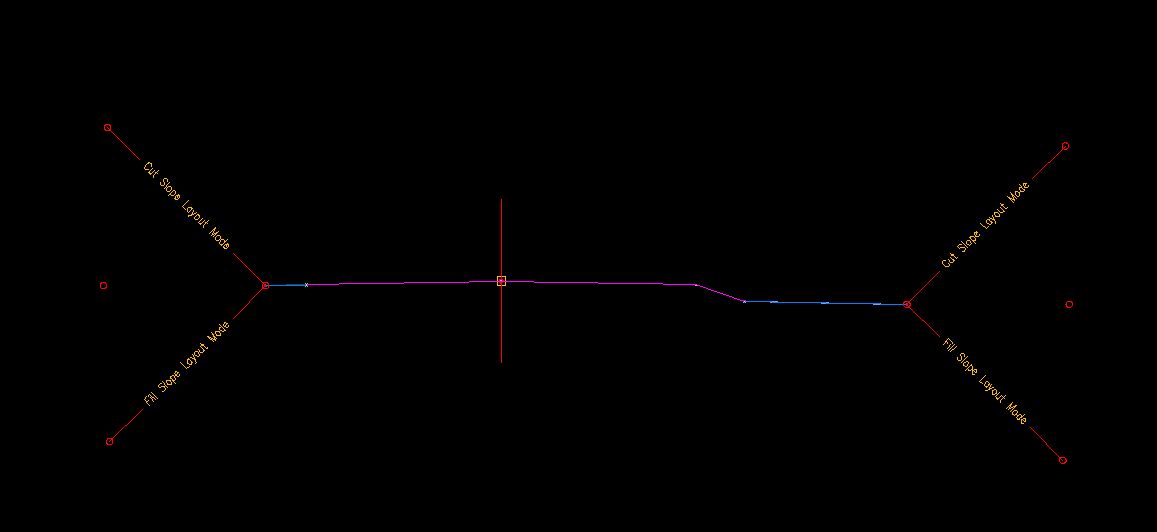
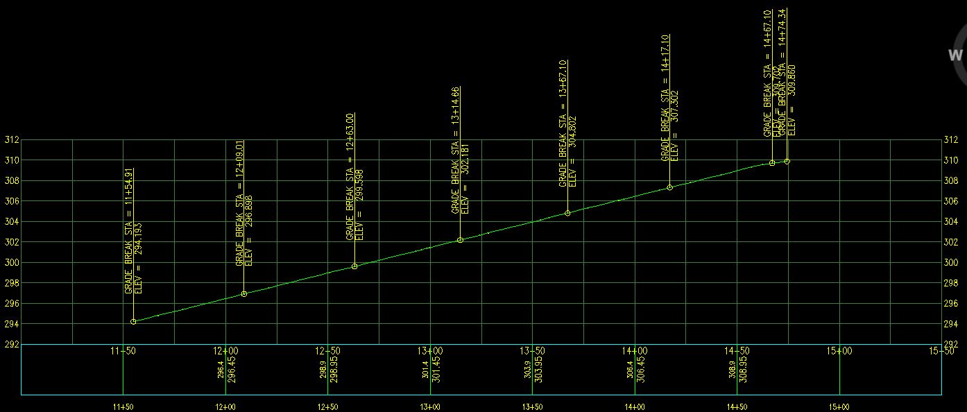
Yes Peter, I will post the screen caps. I tried "LinkSlopetoElevation" and that one seems to help. At least it follows the profile elevation, but there seems to be no way to maintain the 3' min offset as seen towards the end of the alignment (see plan shot).
When I use the "LinkSlopetoElevation" SA and give it a negative slope, it still appears in the assembly to slope upwards. It still works, it just looks odd (last pic).


Message 4 of 17
09-01-2011
06:48 AM
- Mark as New
- Bookmark
- Subscribe
- Mute
- Subscribe to RSS Feed
- Permalink
- Report
09-01-2011
06:48 AM
attachments for better viewing
Message 5 of 17
09-01-2011
06:48 AM
- Mark as New
- Bookmark
- Subscribe
- Mute
- Subscribe to RSS Feed
- Permalink
- Report
09-01-2011
06:48 AM
other pics
Message 6 of 17
09-01-2011
08:43 AM
- Mark as New
- Bookmark
- Subscribe
- Mute
- Subscribe to RSS Feed
- Permalink
- Report
09-01-2011
08:43 AM
it's simple math the first 100 feet the 3 ft shoulder will be within 1:3 slope. from 100 on the walk will need to move away from the road at a rate of 3 ft for ever 100 ft of stationing to maintain 1:3 slope.
Message 7 of 17
09-01-2011
08:44 AM
- Mark as New
- Bookmark
- Subscribe
- Mute
- Subscribe to RSS Feed
- Permalink
- Report
09-01-2011
08:44 AM
Dave,
i've attached a little PKT file created with SAC that I think does what you want it to. It goes out 3 feet and sets the elevation based on the bike path profile. If the slope from the attachment to the test point is over 33% then it slopes at 33% to the elevation of the bike path (pushing the path out). If not, then it slopes for 3' to the bike path elevation.
It doesn't have any point codes, it doesn't maintain 5% (another case where it would have to move the path out), it doesn't work going down or to the left. (It also took about 5 mins to make).
Cheers,
Peter Funk
Autodesk, Inc.
Peter Funk
Autodesk, Inc.
Message 8 of 17
09-01-2011
09:08 AM
- Mark as New
- Bookmark
- Subscribe
- Mute
- Subscribe to RSS Feed
- Permalink
- Report
09-01-2011
09:08 AM
seems simple, but not quite when trying to model.
@Peter. I will try your .pkt file and get back with you.
Message 9 of 17
09-01-2011
10:20 AM
- Mark as New
- Bookmark
- Subscribe
- Mute
- Subscribe to RSS Feed
- Permalink
- Report
09-01-2011
10:20 AM
no luck with the .pkt file It's probably end user error (me). The bike path maintains a 3' offset for the entire length when I apply it. I found another solution using "LinkSlopetoElevation" though. I'll have to study SAC settings because I've never used it. I just downloaded it for the first time.
Thank for the help Peter!
Message 10 of 17
09-01-2011
10:24 AM
- Mark as New
- Bookmark
- Subscribe
- Mute
- Subscribe to RSS Feed
- Permalink
- Report
09-01-2011
10:24 AM
Did target the bike path profile in the corridor?
Peter Funk
Autodesk, Inc.
Peter Funk
Autodesk, Inc.
Message 11 of 17
09-01-2011
10:24 AM
- Mark as New
- Bookmark
- Subscribe
- Mute
- Subscribe to RSS Feed
- Permalink
- Report
Message 12 of 17
09-01-2011
10:54 AM
- Mark as New
- Bookmark
- Subscribe
- Mute
- Subscribe to RSS Feed
- Permalink
- Report
09-01-2011
10:54 AM
Dave,
I just tried it again in 2012 and it worked fine (once I actually hit the "Add" button to target the elevation).
Peter Funk
Autodesk, Inc.
Peter Funk
Autodesk, Inc.
Message 13 of 17
09-01-2011
10:56 AM
- Mark as New
- Bookmark
- Subscribe
- Mute
- Subscribe to RSS Feed
- Permalink
- Report
09-01-2011
10:56 AM
let me try in 2012 then 🙂
Message 14 of 17
09-01-2011
11:03 AM
- Mark as New
- Bookmark
- Subscribe
- Mute
- Subscribe to RSS Feed
- Permalink
- Report
09-01-2011
11:03 AM
no go. The slope changes but the offset remains 3'. I set "TargetParameter1" to target the bike path profile. Does "TargetParameter2" under surfaces need to be set to anything? Also, why is DeltaY set to "10" in the True definition portion? I can send you my drawing file as well if needed. It's around 5 MB.
Message 15 of 17
09-01-2011
11:09 AM
- Mark as New
- Bookmark
- Subscribe
- Mute
- Subscribe to RSS Feed
- Permalink
- Report
09-01-2011
11:09 AM
Send me the file directly... I have a different version of the PKT, but it works exactly the same for me.
Peter Funk
Autodesk, Inc.
Peter Funk
Autodesk, Inc.
Message 16 of 17
09-02-2011
09:37 AM
- Mark as New
- Bookmark
- Subscribe
- Mute
- Subscribe to RSS Feed
- Permalink
- Report
09-02-2011
09:37 AM
@Anonymous wrote:< "BasicLaneTransition" >
I try to stay away from sub assemblies with the word "basic" in the name. Most of thos are for demonstration and learning purposes as the help files often state.
Joe Bouza
Did you find this post helpful? Feel free to Like this post.
Did your question get successfully answered? Then click on the ACCEPT SOLUTION button.
Message 17 of 17
09-06-2011
09:03 AM
- Mark as New
- Bookmark
- Subscribe
- Mute
- Subscribe to RSS Feed
- Permalink
- Report
09-06-2011
09:03 AM
Thanks again Peter for your assistance. Creating a custom subassembly using Subassembly Composer was definitely the answer. You have opened my eyes to a new and very powerful tool! I owe you one.
Best Regards,
Reply
Topic Options
- Subscribe to RSS Feed
- Mark Topic as New
- Mark Topic as Read
- Float this Topic for Current User
- Bookmark
- Subscribe
- Printer Friendly Page
Forums Links
Can't find what you're looking for? Ask the community or share your knowledge.
Post to forums

